Installation Instructions
Temperature-Pressure
Relief Valve
AWARNING
At the time of manufacture this water heater was provid- ed with a combination
Water Supply Systems, and the latest edition of ANSI
Z21.22 and the code requirements of ASME. If replaced, the valve must meet the requirements of local codes, but
not less than a combination temperature and pressure
relief valve certified as meeting the requirements for Relief Valves and Automatic Gas Shutoff Devices for Hot
Water Supply Systems, ANSI Z21.22 by a nationally recog- nized testing laboratory that maintains periodic inspection of production of listed equipment or materials.
The valve must be marked with a maximum set pressure not to exceed the marked hydrostatic working pressure of the water heater (150 IbsJsq.in,) and a discharge capacity not lessthan the water beater input rate as shown on the model rating plate, (Electric heaters - watts divided by 1000 x 3415 equal BTU/Hr. rate.)
Your local jurisdictional authority, while mandating the use of a
Compliance with such local requirements must be satis- fred by the installer or end user of the water heater with a
locally prescribed
For safe operation of the water heater, the relief valve
must not be removed from it'sdesignated opening or plugged.
The
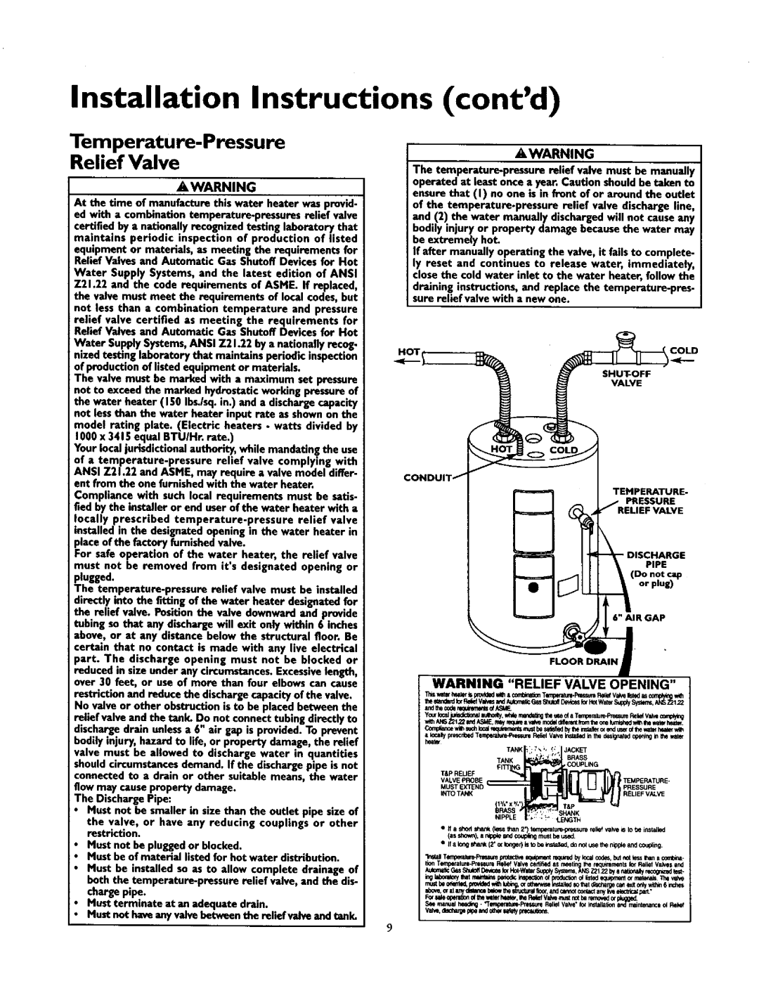
No valve or other obstruction is to be placed between the relief valve and the tank. Do not connect tubing directly to discharge drain unlessa 6" air gap is provided. To prevent bodily injury, hazard to life, or property damage, the relief valve must be allowed to discharge water in quantities should circumstances demand. If the discharge pipe is not connected to a drain or other suitable means, the water flow may cause property damage.
The Discharge Pipe:
Must not be smaller in size than the outlet pipe size of
the valve, or have any reducing couplings or other restriction.
Must not be plugged or blocked.
Must be of material listed for hot water distribution. Must be installed so as to allow complete drainage of beth the
Must terminate at an adequate drain.
Must not have anywdve between the relief wdve and tank.
(cont'd)
_,WARNING
The
bodily injury or property damage because the water may be extremely hot.
If efter manually operating the valve, it fails to complete- ly reset and continues to release water, immediately, close the cold water inlet to the water heater, follow the
draining instructions, and replace the
VALVE
CONDUIT f
TEMPERATURE-
PRESSURE
_ _'RELIEF VALVE
(Do not €_o
Ao-u,,
WARNING "RELIEF VALVE OPENING"
heat_
|
| TANK i | ;"_;, | !: | JACKET |
|
|
| • f. |
| BRASS |
| TANK |
|
| COUpUN G | |
VALVEPROBE |
|
|
| TEMPERATURE- | |
MUST | EXTEND |
|
|
| PRESSURE |
INTO | TANK |
|
|
| RELIEF VALVE |
T&P REUEF |
|
|
|
| |
| NI | , | . t | SHANK | |
e ff a shod _a_ (le_ | Eqan 2') _un_pressgre | lelief valve _ to be irtStalled | |||
(as_orm), a n_ole_d C<X_,_mustbeus_
•If a Io_ sl.,a_ (2'o_lor,geOIs tobei_sta_d, dono_use_e nipf_ a_dcc_,#i_.
T__ralurlPpr_,_ure R_dk_fValve ¢srtihlld as n_li the t_ql_n_ Iof Relief V_Vll ind
nmt be o_d, po,4_d wi_ lubing,orothe_v_ _ | thatdi_arge _ _,_ ody.ith_ 6 _ches ! |