Piping Installation

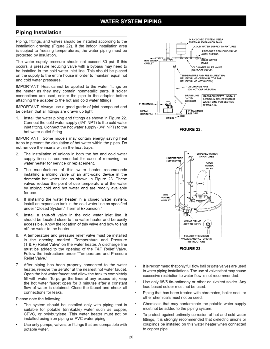
Piping, fittings, and valves should be installed according to the installation drawing (Figure 22). If the indoor installation area is subject to freezing temperatures, the water piping must be protected by insulation.

The water supply pressure should not exceed 80 psi. If this occurs, a pressure reducing valve with a bypass may need to be installed in the cold water inlet line. This should be placed on the supply to the entire house in order to maintain equal hot and cold water pressures.

IMPORTANT: Heat cannot be applied to the water fittings on the heater as they may contain nonmetallic parts. If solder connections are used, solder the pipe to the adapter before attaching the adapter to the hot and cold water fittings.

IMPORTANT: Always use a good grade of joint compound and be certain that all fittings are drawn up tight.

1.Install the water piping and fittings as shown in Figure 22. Connect the cold water supply (3/4" NPT) to the cold water inlet fitting. Connect the hot water supply (3/4" NPT) to the hot water outlet fitting.

IMPORTANT: Some models may contain energy saving heat traps to prevent the circulation of hot water within the pipes. Do not remove the inserts within the heat traps.

2.The installation of unions in both the hot and cold water supply lines is recommended for ease of removing the water heater for service or replacement.

3.The manufacturer of this water heater recommends installing a mixing valve or an anti-scald device in the domestic hot water line as shown in Figure 23. These valves reduce the point-of-use temperature of the water by mixing cold and hot water and are readily available for use.

4.If installing the water heater in a closed water system, install an expansion tank in the cold water line as specified under "Closed System/Thermal Expansion."

5.Install a shut-off valve in the cold water inlet line. It

should be located close to the water heater and be easily accessible. Know the location of this valve and how to shut off the water to the heater.

6, A temperature and pressure relief valve must be installed in the opening marked "Temperature and Pressure (T & P) Relief Valve" on the water heater. A discharge line must be added to the opening of the T&P Relief Valve. Follow the instructions under "Temperature and Pressure Relief Valve."

After piping has been properly connected to the water heater, remove the aerator at the nearest hot water faucet. Open the hot water faucet and allow the tank to completely fill with water. To purge the lines of any excess air, keep the hot water faucet open for 3 minutes after a constant flow of water is obtained. Close the faucet and check all connections for leaks.

Please note the following:

The system should be installed only with piping that is suitable for potable (drinkable) water such as copper, CPVC, or polybutylene. This water heater must not be installed using iron piping or PVC water piping.

Use only pumps, valves, or fittings that are compatible with potable water.


IN A CLOSED SYSTEM, USE A


_THERMAL

.TANK/COLD.


WATEREXPANSIONSUPPLY

TO

FIXTURES


J_

_


r_


PRESSURE

REDUCING

VALVE


]_

_'T'_ U A.,_W_THEYPASS


HOT

WATER


COLD

WATER


OUTLET

ER _

\


_


INLET


TvALvE


TEMPERATURE


AND

PRESSURE


(T&P)


RELIEF

VALVE

(OPTIONAL

TOP T&P


RELIEF

VALVE

NOT

SHOWN)


_---_


DISCHARGE


PIPE


(DO NOT CAP OR PLUG)


DRAIN

LINE


MASSACHUSETTS:

INSTALL


"0_

3/4" ID


AVACUUM

LINE

RELIEF

IN

COLD

1" MINtMUM

--_


MINIMUM


WATER


PER

SECTION


METAL


_'-_

I

/_


_19 MGL

142.


6" MAXIMUM


DRAIN

PAN

--_


T AIR

GAP


DRAIN

/


FIGURE 22.

TO FIXTURES

UNTEMPERED

HOT WATER

COLD

WATER

INLET

HOT

OUTLET

\

(SET TO 120°F)

MIXING VALVE

FOLLOW THE MIXING

VALVE MANUFACTURER'S

INSTRUCTIONS

FIGURE 23.

It is recommend that only full flow ball or gate valves are used in water piping installations. The use of valves that may cause excessive restriction to water flow is not recommended.

Use only 95/5 tin-antimony or other equivalent solder. Any lead based solder must not be used.

Piping that has been treated with chromates, boiler seal, or other chemicals must not be used.

Chemicals that may contaminate the potable water supply must not be added to the piping system.

To protect against untimely corrosion of hot and cold water fittings, it is strongly recommended that dielectric unions or couplings be installed on this water heater when connected to copper pipe.

2O

Page 20
Image 20
Kenmore 153.331592, 153.331492 owner manual TvALvE, Piping Installation

153.331492, 153.331592 specifications

The Kenmore 153.331592 and 153.331492 are two innovative models in a series of versatile and efficient appliances designed to enhance everyday living. These products cater to a wide range of household needs, making them not only practical but also integral to modern home technology.

One of the standout features of the Kenmore 153.331592 is its energy efficiency. Designed with advanced technology, this model consumes less energy while providing robust performance. This is particularly important for environmentally conscious consumers looking to reduce their carbon footprint without compromising on effectiveness. The appliance utilizes smart energy management systems that optimize power use, ensuring that households can enjoy high performance with minimal energy costs.

On the other hand, the Kenmore 153.331492 offers impressive capacity, making it ideal for larger families or those who frequently entertain guests. This model is designed to accommodate substantial loads, whether it be laundry, cooking, or storage, making it a perfect fit for busy households. Additionally, its spacious design allows for easy organization, ensuring that items can be stored efficiently without clutter.

Both models incorporate advanced technology, including intuitive digital controls. These controls allow users to easily set preferences and monitor their appliance's operation through user-friendly interfaces. Smart connectivity features are also integrated into both models, allowing for remote management via smartphone apps. Users can adjust settings, receive alerts, and even perform diagnostics from the convenience of their phones, highlighting Kenmore's commitment to convenience and ease of use.

In terms of build quality, both models exhibit durable construction with high-quality materials designed to withstand the rigors of daily use. The sleek and modern design enhances their aesthetic appeal, making them suitable for any kitchen or laundry room decor.

Additionally, safety features such as auto shut-off, child locks, and overload protection are included in both models, ensuring that they operate smoothly without unnecessary risks.

In conclusion, the Kenmore 153.331592 and 153.331492 stand out for their blend of efficiency, capacity, and smart technology integration. These models present a compelling choice for those seeking reliable appliances that cater to both traditional and modern lifestyles. With a focus on energy conservation, user-friendly interfaces, and durable build quality, Kenmore continues to solidify its reputation as a leader in home appliance innovation.