The Discharge Pipe:
•Shall not be smaller in size than the outlet pipe size of the valve, or have any reducing couplings or other restrictions.
•Shall not be plugged or blocked.
•Shall be of material listed for hot water distribution.
•Shall be installed so as to allow complete drainage of both the
•Shall terminate at an adequate drain.
•Shall not have any valve between the relief valve and tank.
If the main gas line
A gas line of sufficient size must be run to the water heater. Consult the current edition of National Fuel Gas Code ANSI Z223.1/NFPA 54 and your gas supplier concerning pipe size.
There must be:
•A readily accessible manual shut off valve in the gas supply line serving the water heater, and
•A drip leg (sediment trap) ahead of the gas control valve to help prevent dirt and foreign materials from entering the gas control valve.
•A flexible gas connector or a ground joint union between the shut off valve and control valve to permit servicing of the unit.
Be sure to check all the gas piping for leaks before lighting the water heater. Use a soapy water solution, not a match or open flame. Rinse off soapy solution and wipe dry.
The
If after manually operating the valve, it fails to completely reset and continues to release water, immediately close the cold water inlet to the water heater, follow the draining instructions, and replace the
GAS PIPING
Make sure the gas supplied is the same type listed on the model rating plate. The inlet gas pressure must not exceed 14 inch water column (3.5 kPa) for natural and propane gas (L.P.). The minimum inlet gas pressure shown on the rating plate is that which will permit firing at rated input.
All gas piping must comply with local codes and ordinances or with the National Fuel Gas Code (ANSI Z223.1/
If the gas control valve is subjected to pressures exceeding 1/2 psi (3.5 kPa), the damage to the gas control valve could result in a fire or
explosion from leaking gas.
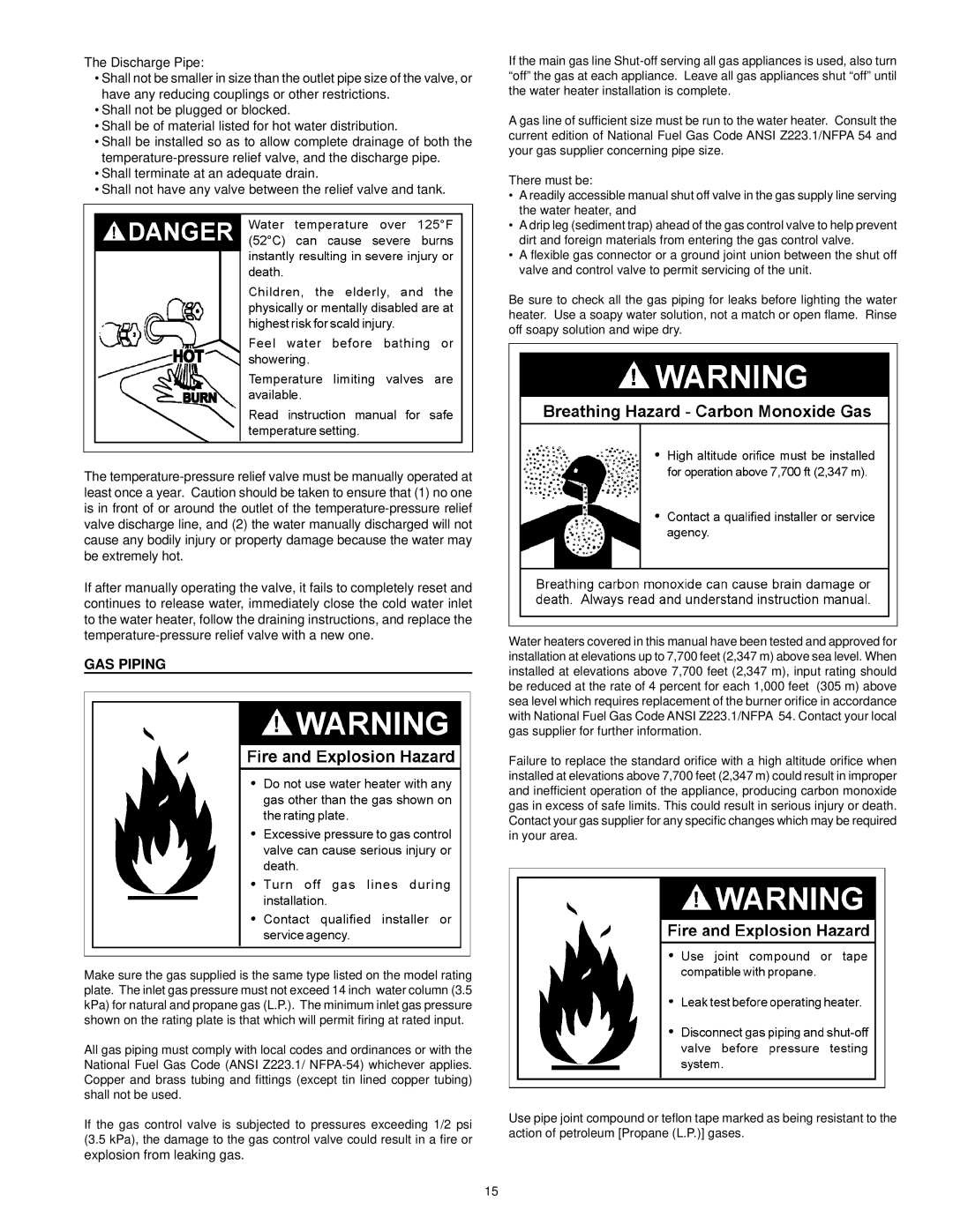
Water heaters covered in this manual have been tested and approved for installation at elevations up to 7,700 feet (2,347 m) above sea level. When installed at elevations above 7,700 feet (2,347 m), input rating should be reduced at the rate of 4 percent for each 1,000 feet (305 m) above sea level which requires replacement of the burner orifice in accordance with National Fuel Gas Code ANSI Z223.1/NFPA 54. Contact your local gas supplier for further information.
Failure to replace the standard orifice with a high altitude orifice when installed at elevations above 7,700 feet (2,347 m) could result in improper and inefficient operation of the appliance, producing carbon monoxide gas in excess of safe limits. This could result in serious injury or death. Contact your gas supplier for any specific changes which may be required in your area.
Use pipe joint compound or teflon tape marked as being resistant to the action of petroleum [Propane (L.P.)] gases.
15