TS-440S

CIRCUIT DESCRIPTIO N

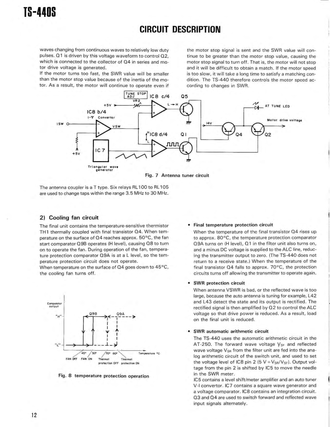
waves changing from continuous waves to relatively low duty pulses . Q1 is driven by this voltage waveform to control Q2 , which is connected to the collector of Q4 in series and mo- tor drive voltage is generated .

If the motor turns too fast, the SWR value will be smalle r than the motor stop value because of the inertia of the mo- tor . As a result, the motor will continue to operate even if

TUNE STO P

ADJ IC8 c/4

the motor stop signal is sent and the SWR value will con- tinue to be greater than the motor stop value, causing th e motor stop signal to turn off . That is, the motor will not sto p and it will be difficult to obtain a match . If the motor spee d is too slow, it will take a long time to satisfy a matching con - dition . The TS-440 therefore controls the motor speed ac - cording to changes in SWR .

Q 5

Triangular wov e generator

Fig . 7 Antenna tuner circuit

The antenna coupler is a T type . Six relays RL100 to RL10 5 are used to change taps within the range 3 .5 MHz to 30 MHz .

2) Cooling fan circuit

The final unit contains the temperature-sensitive thermisto r TH1 thermally coupled with final transistor Q4 . When tem- perature on the surface of Q4 reaches approx . 50°C, the fa n start comparator Q9B operates (H level), causing Q8 to tur n on to operate the fan . During operation of the fan, tempera - ture protection comparator Q9A is at a L level, so the tem- perature protection circuit does not operate .

When temperature on the surface of Q4 goes down to 45°C , the cooling fan turns off .

Comparato r output

Q9 B

V

/45° /50°

0° Bo°

Temperature ° C

FAN OFF FAN ON

Thermal

Therma l


protection OFF protection ON

Fig . 8 temperature protection operatio n

Final temperature protection circuit

When the temperature of the final transistor Q4 rises u p to approx . 80°C, the temperature protection comparato r Q9A turns on (H level), Q1 in the filter unit also turns on , and a minus DC voltage is supplied to the ALC line, reduc - ing the transmitter output to zero . (The TS-440 does not return to a receive state .) When the temperature of th e final transistor Q4 falls to approx . 70°C, the protectio n circuits turns off allowing the transmitter to operate again .

SWR protection circuit

When antenna VSWR is bad, or the reflected wave is to o large, because the auto antenna is tuning for example, L4 2 and L43 detect the state and its output is rectified . Th e rectified signal is then amplified by Q2 to control the AL C voltage so that drive power is reduced . As a result, loa d on the final unit is reduced .

SWR automatic arithmetic circuit

The TS-440 uses the automatic arithmetic circuit in th e AT-250 . The forward wave voltage VSF and reflecte d wave voltage VSR from the filter unit are fed into the ana - log arithmetic circuit of the switch unit, and used to se t the voltage level of IC8 pin 2 (5 V +VsR/VSF) . Output vol- tage from the pin 2 is shifted by IC5 to move the needl e in the SWR meter .

IC5 contains a level shift/meter amplifier and an auto tune r V-I convertor . IC7 contains a square wave generator an d a voltage comparator . IC8 contains an integration circuit . Q3 and Q4 are used to switch forward and reflected wave input signals alternately .

12

Page 12
Image 12
Kenwood PS-430, PS-50, SP-430, MB-430 Fig Antenna tuner circuit, SWR protection circuit, SWR automatic arithmetic circuit

SP-430, VS-1, PS-430, AT-440, YK-88C specifications

The Kenwood MB-430, PS-50, YK-88S, YK-88CN, and YK-88SN are notable components that enhance the capabilities of Kenwood's transceiver products, particularly in the amateur radio segment. Each of these units plays an essential role in expanding functionality, improving performance, and providing users with valuable features that are beneficial in various communication scenarios.

Starting with the Kenwood MB-430, it serves as a versatile mobile bracket designed for specific Kenwood radio models. The MB-430 enhances mobility, allowing operators to mount their radios securely in vehicles or portable setups. Its sturdy construction ensures reliability during operation, and it offers a simple installation process, making it user-friendly for both beginners and seasoned enthusiasts.

The PS-50 power supply is a crucial accessory that complements Kenwood's transceiver line. This power supply is known for its compact design, providing 13.8 V DC output, which is essential for powering radios effectively. With a current rating that adequately supports various transceivers, the PS-50 is equipped with short-circuit protection and thermal overload features. These safety mechanisms protect both the power supply and the connected equipment, making it a dependable choice amongst operators.

The YK-88S, YK-88CN, and YK-88SN are all filters that enhance the performance of Kenwood transceivers. The YK-88S is a high-performance SSB filter, designed to improve the clarity of SSB signals while reducing adjacent channel interference. It offers narrow bandwidth options that facilitate more precise tuning, making it particularly valuable in crowded band conditions.

Meanwhile, the YK-88CN is known for its crystal filter technology, optimizing the transceiver's performance for CW and digital modes. This filter helps in eliminating unwanted noise, allowing operators to enjoy clearer reception and improved decoding of weak signals.

The YK-88SN, similar in function to the YK-88S and YK-88CN, provides additional narrow filtering options, enhancing the agility of transceiver operation in various modes. It effectively enhances selectivity and reduces interference from strong signals, providing a cleaner audio output.

Together, these components contribute to a seamless operating experience for amateur radio enthusiasts. Whether enhancing filter characteristics, providing reliable power, or ensuring secure mobility, the MB-430, PS-50, YK-88S, YK-88CN, and YK-88SN demonstrate Kenwood’s commitment to quality and performance in the radio communications field.