4. Static input

7800 (ICI)

CO

Encoder U/D signa l

C 2

Unlock signa l

074052 (IC : Display)

8255 (IC53 )

BO

Lock switc h

B2

AT switc h

B3

MIC UP switc h

B4

MIC DOWN switc h

B5

PTT switc h

B7

VS-1 busy signal

CIRCUIT DESCRIPTIO N

"H" when U P


"L" when unloc k


A/D convertor dat a

A K


D O

"L" when switch o n


"L" when switch o n


"L" when switch o n


"L" when switch o n


"L" when switch o n


"H" when VS-1 busy


TS-440S

2 --%--- 1 9 L

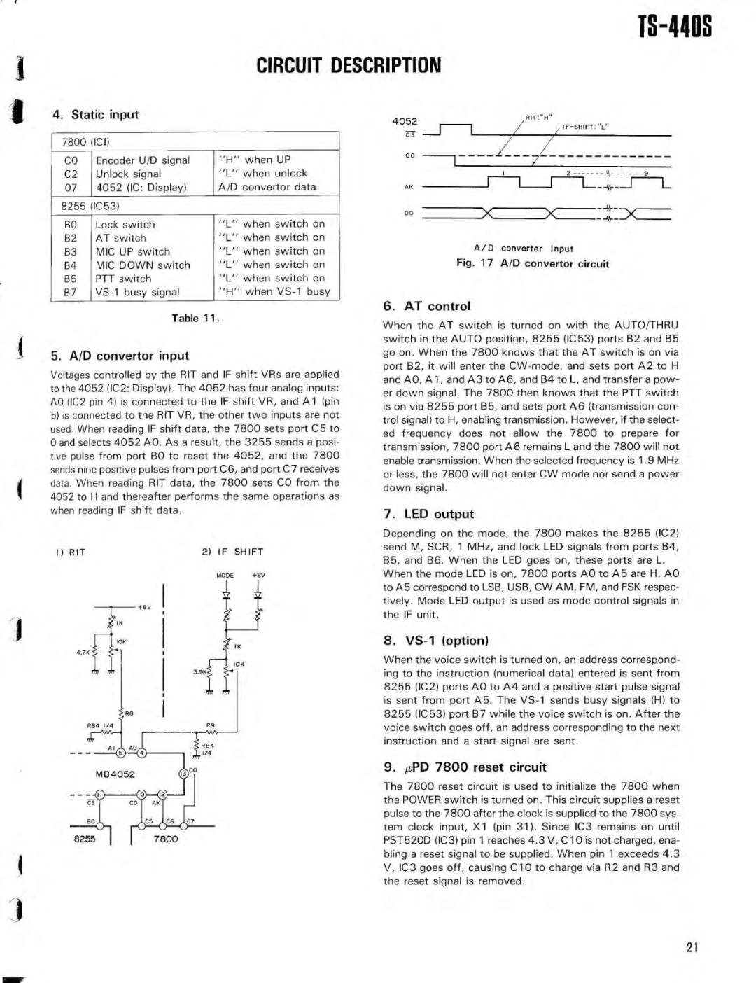
A/D converter Inpu t

Fig . 17 A/D convertor circui t

Table 1 1 .

5 . A/D convertor inpu t

Voltages controlled by the RIT and IF shift VRs are applie d to the 4052 (IC2 : Display) . The 4052 has four analog inputs : AO (IC2 pin 4) is connected to the IF shift VR, and Al (pi n

5)is connected to the RIT VR, the other two inputs are not used . When reading IF shift data, the 7800 sets port C5 t o 0 and selects 4052 AO . As a result, the 3255 sends a posi - tive pulse from port BO to reset the 4052, and the 780 0 sends nine positive pulses from port C6, and port C7 receive s data . When reading RIT data, the 7800 sets CO from th e 4052 to H and thereafter performs the same operations as when reading IF shift data .

I) RIT

2) IF SHIFT

6 . AT control

When the AT switch is turned on with the AUTO/THR U switch in the AUTO position, 8255 (IC53) ports B2 and B 5 go on . When the 7800 knows that the AT switch is on vi a port B2, it will enter the CW-mode, and sets port A2 to H and A0, Al, and A3 to A6, and B4 to L, and transfer a pow- er down signal . The 7800 then knows that the PTT switc h is on via 8255 port B5, and sets port A6 (transmission con- trol signal) to H, enabling transmission . However, if the select - ed frequency does not allow the 7800 to prepare fo r transmission, 7800 port A6 remains L and the 7800 will not enable transmission . When the selected frequency is 1 .9 MH z or less, the 7800 will not enter CW mode nor send a powe r down signal .

7. LED outpu t

Depending on the mode, the 7800 makes the 8255 (IC2 ) send M, SCR, 1 MHz, and lock LED signals from ports B4 , B5, and B6 . When the LED goes on, these ports are L .

When the mode LED is on, 7800 ports AO to AS are H . AO to A5 correspond to LSB, USB, CW AM, FM, and FSK respec - tively . Mode LED output is used as mode control signals i n the IF unit .

8. VS-1 (option )

When the voice switch is turned on, an address correspond- ing to the instruction (numerical data) entered is sent fro m 8255 (IC2) ports AO to A4 and a positive start pulse signa l is sent from port A5 . The VS-1 sends busy signals (H) to 8255 (IC53) port B7 while the voice switch is on . After th e voice switch goes off, an address corresponding to the nex t instruction and a start signal are sent .

MB 4052

9. µPD 7800 reset circuit

I

The 7800 reset circuit is used to initialize the 7800 whe n the POWER switch is turned on . This circuit supplies a rese t pulse to the 7800 after the clock is supplied to the 7800 sys - tem clock input, X1 (pin 31) . Since IC3 remains on unti l PST520D (IC3) pin 1 reaches 4 .3 V, C10 is not charged, ena - bling a reset signal to be supplied . When pin 1 exceeds 4 . 3 V, IC3 goes off, causing C10 to charge via R2 and R3 an d the reset signal is removed .

2 1

Page 21
Image 21
Kenwood SP-430, PS-50, PS-430, MB-430, AT-440, VS-1, YK-88SN, YK-88CN 1 9 L, Fig A/D convertor circui t, RIT If Shift

SP-430, VS-1, PS-430, AT-440, YK-88C specifications

The Kenwood MB-430, PS-50, YK-88S, YK-88CN, and YK-88SN are notable components that enhance the capabilities of Kenwood's transceiver products, particularly in the amateur radio segment. Each of these units plays an essential role in expanding functionality, improving performance, and providing users with valuable features that are beneficial in various communication scenarios.

Starting with the Kenwood MB-430, it serves as a versatile mobile bracket designed for specific Kenwood radio models. The MB-430 enhances mobility, allowing operators to mount their radios securely in vehicles or portable setups. Its sturdy construction ensures reliability during operation, and it offers a simple installation process, making it user-friendly for both beginners and seasoned enthusiasts.

The PS-50 power supply is a crucial accessory that complements Kenwood's transceiver line. This power supply is known for its compact design, providing 13.8 V DC output, which is essential for powering radios effectively. With a current rating that adequately supports various transceivers, the PS-50 is equipped with short-circuit protection and thermal overload features. These safety mechanisms protect both the power supply and the connected equipment, making it a dependable choice amongst operators.

The YK-88S, YK-88CN, and YK-88SN are all filters that enhance the performance of Kenwood transceivers. The YK-88S is a high-performance SSB filter, designed to improve the clarity of SSB signals while reducing adjacent channel interference. It offers narrow bandwidth options that facilitate more precise tuning, making it particularly valuable in crowded band conditions.

Meanwhile, the YK-88CN is known for its crystal filter technology, optimizing the transceiver's performance for CW and digital modes. This filter helps in eliminating unwanted noise, allowing operators to enjoy clearer reception and improved decoding of weak signals.

The YK-88SN, similar in function to the YK-88S and YK-88CN, provides additional narrow filtering options, enhancing the agility of transceiver operation in various modes. It effectively enhances selectivity and reduces interference from strong signals, providing a cleaner audio output.

Together, these components contribute to a seamless operating experience for amateur radio enthusiasts. Whether enhancing filter characteristics, providing reliable power, or ensuring secure mobility, the MB-430, PS-50, YK-88S, YK-88CN, and YK-88SN demonstrate Kenwood’s commitment to quality and performance in the radio communications field.