TS-440S

CIRCUIT DESCRIPTION

t

Signals from the ANT pin are fed into the RAT pin of the R F


unit via the transmit/receive switching relay . The signals the n


go to the 10 BPFs through the approx . 20 dB attenuator cir-


cuit, the first stage of the first IF trap circuit, and the lo w


pass filters (which pass only 500 kHz or less) . The signal the n


goes through the second stage of the first IF trap circuit, an d


is mixed with the VCO signal and converted into the first I F


signal of 45 .05 MHz in the first mixer, consisting of Q3 an d


Q4 (2SK125-5) . The VCO circuit consists of Q21 to Q2 4


(2SC2668Y) and oscillates in four bands from 45 .05 MH z


to 75 .05 MHz . Oscillator frequencies are controlled by D C


signals from the PLL unit .


The first IF signal of 45 .05 MHz is passed through the MC F


(F1), which is used in both receive and transmit, and is am -


plified by the first IF amplifier Q5 (3SK74L) . In the secon d


mixer, consisting of Q6 and Q7 (2SK1 25), the first IF signa l


is mixed with the heterodyne oscillator signal (36 .22 MHz )


from the PLL circuit, amplified by Q12 (2SC2668Y) to ob-


tain the second IF signal (8 .83 MHz) . The second IF signa l


of 8 .83 MHz goes through the gate of the noise blanker . In


modes other than FM , the signal then goes through the MC F


(F2) and is fed into the IF unit through buffer amplifiers Q 8


and Q9 (2SC2668Y) .

When the optional 8 .83 MHz filter is connected, the secon d IF signal is then fed from the IF unit into the optional filter . In the third mixer, consisting of Q1 and Q2 (3SK73GR), th e second IF signal is mixed with 8 .375 MHz signal generate d by IF unit's heterodyne oscillator circuit, consisting of Q5 3 and Q54 (2SC2458Y), and converted into the third IF signa l (455 kHz) . The third IF signal is then amplified by Q 5 (3SK73GR) . A diode switch is used to route the signal t o either the FM or SSB circuits .

In SSB mode, the third IF signal goes through the SSB cer- amic filter (XF3) . In AM mode, the third IF signal goes throug h the AM ceramic filter (XF4) . In either mode, the third IF sig- nal is then amplified by Q7 and Q8 (3SK73GR) and detected . In FM mode, the third IF signal goes through the FM cerami c filter (XF5) . The signal is then sent to the FM IF, IC2 (M C 3357) for amplification and detection . IC2 also contains an FM noise squelch circuit .

The detected SSB/AM signal is passed through the notch cir - cuit, consisting of hybrid IC IC1 (BX6124) and squelch gat e Q12 (2SC2459BL) . The signal then goes through the AF volume control and is amplified to the appropriate level b y AF amplifier IC7 (UPC2002V) .

1) Selectivity circui t

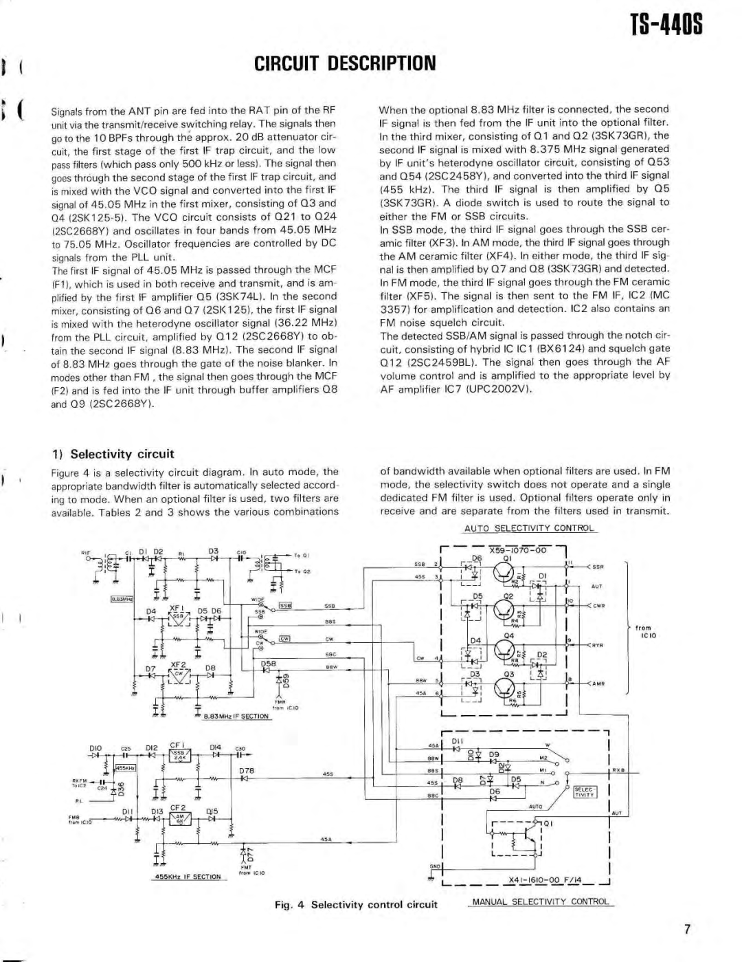
Figure 4 is a selectivity circuit diagram . In auto mode, th e appropriate bandwidth filter is automatically selected accord - ing to mode . When an optional filter is used, two filters ar e available . Tables 2 and 3 shows the various combinations

of bandwidth available when optional filters are used . In F M mode, the selectivity switch does not operate and a singl e dedicated FM filter is used . Optional filters operate only i n receive and are separate from the filters used in transmit .

AUTO SELECTIVITY CONTRO L


I


il aD6

X59—1070—00

1I < ss R

558

21,


01


455 3t_.14

/a

D I

AI


+R+z.'

,$W

AL T


D5

02

L aJ


r p1


< cw R


I


R4~~


fro m


04


D4


IC 1 0


RYR


~• 14

i

D 2


j


D3

0 3


Bew

sj


r al

—i


L_ . J

<A M R

45A

6


L


45AI

DII


BowI

la

o


D


I49 N -

M 2

RX B

455

88 5


(-

0


D8

D 5


45S


a


SELEC-


BBC


6


TIVIT Y

AUTO

AUT n

454

GNDI

F/14 — J

Fig . 4 Selectivity control circuit

MANUAL SELECTIVITY CONTROL

7

Page 7
Image 7
Kenwood PS-50, SP-430, PS-430, MB-430, AT-440, VS-1, YK-88C, YK-88SN Circuit Description, Fig Selectivity control circuit

SP-430, VS-1, PS-430, AT-440, YK-88C specifications

The Kenwood MB-430, PS-50, YK-88S, YK-88CN, and YK-88SN are notable components that enhance the capabilities of Kenwood's transceiver products, particularly in the amateur radio segment. Each of these units plays an essential role in expanding functionality, improving performance, and providing users with valuable features that are beneficial in various communication scenarios.

Starting with the Kenwood MB-430, it serves as a versatile mobile bracket designed for specific Kenwood radio models. The MB-430 enhances mobility, allowing operators to mount their radios securely in vehicles or portable setups. Its sturdy construction ensures reliability during operation, and it offers a simple installation process, making it user-friendly for both beginners and seasoned enthusiasts.

The PS-50 power supply is a crucial accessory that complements Kenwood's transceiver line. This power supply is known for its compact design, providing 13.8 V DC output, which is essential for powering radios effectively. With a current rating that adequately supports various transceivers, the PS-50 is equipped with short-circuit protection and thermal overload features. These safety mechanisms protect both the power supply and the connected equipment, making it a dependable choice amongst operators.

The YK-88S, YK-88CN, and YK-88SN are all filters that enhance the performance of Kenwood transceivers. The YK-88S is a high-performance SSB filter, designed to improve the clarity of SSB signals while reducing adjacent channel interference. It offers narrow bandwidth options that facilitate more precise tuning, making it particularly valuable in crowded band conditions.

Meanwhile, the YK-88CN is known for its crystal filter technology, optimizing the transceiver's performance for CW and digital modes. This filter helps in eliminating unwanted noise, allowing operators to enjoy clearer reception and improved decoding of weak signals.

The YK-88SN, similar in function to the YK-88S and YK-88CN, provides additional narrow filtering options, enhancing the agility of transceiver operation in various modes. It effectively enhances selectivity and reduces interference from strong signals, providing a cleaner audio output.

Together, these components contribute to a seamless operating experience for amateur radio enthusiasts. Whether enhancing filter characteristics, providing reliable power, or ensuring secure mobility, the MB-430, PS-50, YK-88S, YK-88CN, and YK-88SN demonstrate Kenwood’s commitment to quality and performance in the radio communications field.