5.
5-1. GENERAL INFORMATION
Your transceiver has been factory aligned and tested to specification before shipment. Under normal circum- stances the transceiver will operate in accordance with
these operating instructions. All adjustable trimmers and coils in your transceiver were preset at the facto- ry and should only be readjusted by a qualified techni- cian with proper test equipment.
Attempting service or alignment without factory
authorization can void the transceiver's warranty.
When operated properly, the transceiver can give years of service without requiring realignment. The informa- tion in this section gives some general service proce-
dures which can be accomplished without
sophisticated test equipment.
5-2. SERVICE
Should it ever become necessary to return the equip- ment to your dealer or service center for repair, pack in its original box and packing, and include a full description of the problems involved. Also include your telephone number. You need not return accessory items unless directly related to the service problem.
You may return your radio for service to the Autho-
rized
with the unit. Please do not send
Tag all returned items with your name and call for iden- tification. Please mention the model and serial num- ber of your radio in any correspondence, whether phone or written. For future reference, record this in-
5-4. IN CASE OF DIFFICUL TV
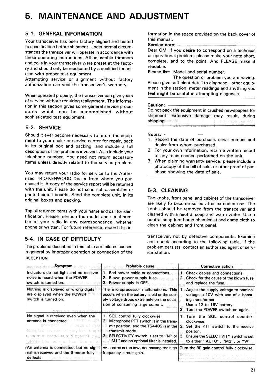
The problems described in this table are failures caused in general by improper operation or connection of the
RECEPTION
formation in the space provided on the back cover of this manual.
Service note:
Dear OM, if you desire to correspond on a technical or operational problem, please make your note short, complete, and to the point. And PLEASE make it readable.
Please list: Model and serial number.
The question or problem you are having. Please give sufficient detail to diagnose: other equip- ment in the station, meter readings and anything you feel might be useful in attempting diagnosis.
Notes:
1.Record the date of purchase, serial number and dealer from whom purchased.
2.For your own information, retain a written record of any maintenance performed on the unit.
3.When claiming warranty service, please include a photocopy of the bill of sale, or other proof of pur- chase showing the date of sale.
5-3. CLEANING
The knobs, front panel and cabinet of the transceiver are likely to become soiled after extended use. The knobs should be removed from the transceiver and cleaned with a neutral soap and warm water. Use a neutral soap (not harsh chemicals) and damp cloth to clean the cabinet and front panel.
transceiver, not by defective components. Examine and check according to the following table. If the problem persists, contact an authorized agent or serv- ice station.
Symptom
Indicators do not light and no receiver noise is heard when the POWER switch is turned on.
Nothing is displayed or wrong digits are displayed when the POWER switch is turned on.
I'JOsignal IS received even when the
antenna is connected.
An antenna is connected, but no sig nal is received and the
|
|
| Probable | cause |
|
|
| Correctiveaction |
| ||||||||
1. | Bad | power | cable | or | connections, | Check | cables and | connections. |
| ||||||||
2. | Blown power supply fuse. |
|
| Check for the cause of the blown fuse | |||||||||||||
3. | Power supply | is | OFF. |
|
|
| and replace | the fuse. |
|
|
| ||||||
The | microprocessor |
| malfunctions. |
| ThiS; | 1. Adjust the supply voltage to nominal | |||||||||||
occurs | when | the | battery | is old or | the | sup- | voltage | :f: 10V with | use | of a | boost- | ||||||
ply | voltage | drops | extremely | on the | ing transformer. |
|
|
|
| ||||||||
sion | of | consuming | large | current. |
|
| Use a | 12 to | 16V | battery. |
|
| |||||
|
|
|
|
|
|
|
|
|
|
| 2. Turn the POWER switch on again. | ||||||
1. ~UL control tully clockwise. |
|
| 1. Turn | the | SQL | control | counter- | ||||||||||
2. | Microphone | PTT switch | is in the | trans- | clockwise. |
|
|
|
|
| |||||||
| mit | position, | and the TS440S | is in the | 2.. Set the PTT switch | to | the | receive | |||||||||
| transmit | mode. |
|
|
|
|
| positon. |
|
|
|
|
| ||||
3. SELECTIVITY switch is set to "N" or 3. Ensure the SELECTIVITY switch is set
"M 1" | and no optional filter is installed. | to | either | "AUTO", | "M2", | or "W" | |
tit- control | IS too | lOW. decreasing the high | I urn | the RF | gain control | fully | clockwise. |
~requency | circuit | gain.! |
|
|
|
|
|
21
