3-8. AFSK
Note:
An RTTY terminal is required to receive and dis- play/print the RTTY signal.
1.The AFSK mode utilizes the LSB carrier frequency, which conforms to international conventions.
2.When the optional
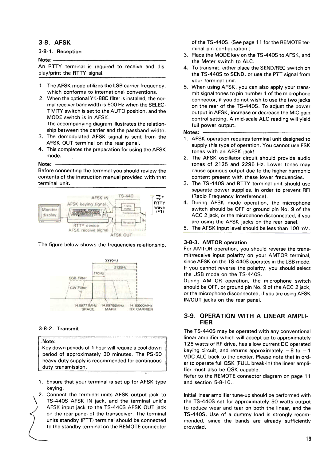
The accompanying diagram illustrates the relation- ship between the carrier and the passband width.
3.The demodulated AFSK signal is sent from the AFSK OUT terminal on the rear panel.
4.This completes the preparation for using the AFSK
mode.
Note: ![]()
![]() - Before connecting the terminal you should review the contents of the instruction manual provided with that terminal unit.
- Before connecting the terminal you should review the contents of the instruction manual provided with that terminal unit.
RTTY
wave
(F1 )
The figure below shows the frequencies relationship.
2295Hz
of the
3.Place the MODE key on the
4.To transmit, either place the SEND/REC switch on the
5.When using AFSK, you can also apply your trans- mit signal tones to pin number 1 of the microphone connector, if you do not wish to use the two jacks on the rear of the
Notes:
1.AFSK operation requires terminal unit designed to supply this type of operation. You cannot use FSK tones with an AFSK jack!
2.The AFSK oscillator circuit should provide audio tones of 2125 and 2295 Hz. Lower tones may cause spurious output due to the higher harmonic content present with these lower frequencies.
3.The
4.During AFSK mode operation, the microphone switch should be OFF or ground pin No.9 of the ACC 2 jack, or the microphone disconnected, if you are using the AFSK jacks on the rear panel.
5.The AFSK input level should be less than 100 mV.
For AMTOR operation, you should reverse the trans- mit/receive input polarity on your AMTOR terminal, since AFSK on the
During AMTOR operation, the microphone switch should be OFF, or ground pin No.9 of the ACC 2 jack, orthe microphone disconnected, if you are using AFSK IN/OUT jacks on the rear panel.
Note:
Key down periods of 1 hour will require q cool down period of approximately 30 minutes. The
1.Ensure that your terminal is set up for AFSK type keying.
2.Connect the terminal units AFSK output jack to
\
on the rear panel of the transceiver. The terminal units standby (PTT) terminal should be connected to the standby terminal on the REMOTE connector
3-9. OPERATION WITH A LINEAR AMPLI- FIER
The
keying circuit, and returns approximately
Refer to the REMOTE connector diagram on page 11 and section
Initial linear amplifier
the
crowded.
19
~
