AIR-CONDITIONER
Contents
Replacement
Explanation of illustrated marks
Explanation of indications
Confirmation of warning label on the main unit
Indication Explanation
Never recover the refrigerant into the outdoor unit
∗ For details, refer to the parts list
Catch the inner wires
Do not modify the products
Metal section Earth position
Check the following items after reinstallation
Limit even if the refrigerant leaks
After repair work has finished, check there is no trouble
Pipe Materials
Safety Caution Concerned to New Refrigerant
Copper pipe Piping
Flare nut
Used tool Usage
General tools Conventional tools can be used
RAV-SM2244AT series Simultaneous twin
Combination Pattern Indoor Unit / Outdoor Unit
Simultaneous triple
Simultaneous double twin
RAV-SM2804AT series Branch kit
RAV-SM2244AT series Branch kit
Twin type
Indoor Unit
Way Cassette Type
Duct Type Twin type
Ceiling Type Twin type
Way Cassette Type Triple type
Duct Type Triple type
Ceiling Type Triple type
High Wall Type Triple type
Way Cassette Type Double twin type
RAV-SM562MUT-E
Compact 4-Way Cassette 600 × 600 Type Double twin type
RAV-SM564SDT-E
Slim Duct Type Double twin type
Duct Type Double twin type
Ceiling Type Double twin type
High Wall Type Double twin type
2244AT8-E 2804AT8-E 2244AT7 2804AT7
Model Outdoor unit
RAV-SM2244AT7 Z ZG, RAV-SM2804AT7 Z ZG
Operation characteristic curve Digital Inverter
RAV-SM2244AT8 Z ZG -E, RAV-SM2804AT8 Z ZG -E
Cooling Heating
Capacity variation ratio according to temperature
Construction Views External Views
Model ’ty
RBC-DTWP101E Simultaneous Double Twin Branch pipe
Joint pipe
Liquid side
Gas side
RBC-TRP100E Simultaneous Triple
Gas side socket
Gas side 25.4 15.9 Liquid side 12.7
RBC-TWP101E Simultaneous Twin Branch pipe
Outdoor Unit Refrigeranting Cycle Diagram
RAV-SM2804 series
Systematic diagram of refrigerating cycle
RAV-SM2244 series
Wiring Diagram
Parts name Type Specifications
Specifications of Electrical Parts
Copper Pipes
Safety During Installation/Servicing
Piping Materials and Joints Used
Processing of Piping Materials
Flare Processing Procedures and Precautions
Joints
Flare and flare nut dimensions for R410A
3 Dimensions related to flare processing for R410A / R22
Flare and flare nut dimensions for R22
R410A R22 R410A, R22 Clutch type Wing nut type
Wrenches available on the market
Flare Connecting Procedures and Precautions
Nm kgfm
Required Tools
1 Configuration of refrigerant charging
Flux Reason why flux is necessary
Low temperature brazing filler
Materials for Brazing Silver brazing filler
Phosphor bronze brazing filler
Types of flux
Characteristics required for flux
Piping materials for brazing and used brazing filler/flux
Brazing
Restricted Items to Use the Existing Pipes
Basic Conditions Needed to Reuse the Existing Pipe
Branching Pipe for Simultaneous Operation System
Curing of Pipes
Existing pipe SW Switch
Final Installation Checks
Handling of Existing Pipe
Recovering Refrigerant
Print Circuit Board, MCC-1596 Compressor Ipdu
Circuit Configuration and Control Specifications
Outdoor Unit Control
CN700 Blue CN500 Red
Print Circuit Board, MCC-1597 Fan Motor Ipdu
CN504 Blue
F500
Print Circuit Board, MCC-1599 Interface CDB
Print Circuit Board, MCC-1600 Noise Filter
PMV Pulse Motor Valve control
Discharge temperature release control
Outline of Main Controls
Cooling fan control
Outdoor fan revolution number control
Heating fan control
Fan Taps Revolution number Allocation rpm
Electrical current release control
Defrost control
Short interrupted operation preventive control
High-pressure switch/Compressor case thermostat control
Heat sink temperature detection control
Electrical current release value shift control
Over-current protective control
12. SV2 valve control
Oil recovery control
To ˚C
Coil heating control
Summary of Troubleshooting
Troubleshooting
Before troubleshooting
Troubleshooting procedure
Trouble Confirmation of lamp display
Wireless remote controller type
Outline of judgment
Troubleshooting
Lamp indication
Cause of trouble occurrence
Lamp indication Check code Cause of trouble occurrence
Lamp indication Check code
Others Other than Check Code
Monitor Function of Remote Controller Switch
Way valve inverse error
Check Code List Outdoor
Representative defective position
Cause of operation Status
Error mode detected by indoor unit
Series
Error mode detected by outdoor unit
H03 Current detection circuit error Stop
Power supply error of remote controller, Indoor
LED display on outdoor P.C. board Dip switch setup
Diagnostic Procedure for Each Check Code Outdoor Unit
Latest error display
Error display, which occurs at present
F07 Display Display 2 Heat exchanger temp. sensor TL error
Display Display 2 Heat exchanger temp. sensor TE error
Display Heat exchanger temp. sensor TL error →
F13 Display 1 Display 2 Heat sink temp. sensor TH error
F12 Display Display 2 Suction temp. sensor TS error
H01 Display 1 Display 2 Compressor break down
F31 Display 1 Display 2 Eeprom error
H04 Display 1 Display 2 Case thermostat operation
H03 Display Display 2 Current detection circuit error
L10 Display
Display 1 Display 2 Unset model type → Refer to L10 column
Display Display 2 Communication error between MCU
P04
Display High pressure SW system error
Display Display 2 High pressure protective operation →
Display Case thermostat operation → Refer to H04 column
P15 Display Gas leak detection
P07 Display Heat sink overheat error
P19 Display Way valve inverse error
Cooling season
Single operation check for outdoor fan
Position detection circuit error
P26
Display 2 Short-circuit of compressor drive element
TA, TC, TCJ, TE, TS, to sensors
Temperature sensor
TD, TL sensors
Representative value
Group Control Operation
Setup AT Local Site and Others
Calling of Error History
By feed unit Automatic address judgment
Indoor unit power-ON sequence
Initial communication
Usual regular communication
Defrost control
Function Set position Control contents
Display part
Specifications Operation contents
Operation part
Display selection list
Switch Function / Contents Refer
Others Selection of LED display SW800, SW803 operation
¥¥ll¡
Error display
Display
Setup
Pressure
Kg/cm²G
Specific operation
Specific operation for maintenance check SW801, SW804
SW804 Operation when pushdown button switch SW801 is pushed
For check RY703, CN703 check
Address Setup Procedure
Address Setup
Terminology
Address Setup & Group Control
System Configuration
Example
Automatic Address Example from Unset Address No miswiring
Only turning on source power supply Automatic completion
Standard One outdoor unit Single Twin Triple
Wiring diagram
Remote Controller Wiring
Simultaneous twin system
Simultaneous triple and double twin system
Address Setup Manual setting from remote controller
To know the position of indoor unit body by address
Confirmation of Indoor Unit No. Position
Button
Button if the unit stops
Part name Object Contents of check Contents of maintenance
Maintenance/Check list
Contents
New Refrigerant Air Conditioner Installation
Connect the connecting wire correctly
When using the conventional piping
Tools/equipment Use How to use tools/equipment
When using general copper pipes
Flare nuts and flare machining
100
Parts name ’ty
101
102
Total length Branch piping Indoor-outdoor H
Allowable pipe length m
Upper Maximum SM2244 SM2804
Pipe diameter mm
104
Connected, and fix wires securely so that the external
Using the specified wires, ensure that the wires are
Tension to the wires does not affect the connecting
Be sure to connect the earth wire grounding work
Check the following before starting a test run
106 8 Earthing
That all pipes are connected securely without leaks
That the valve is open
Reference outside Wall thickness Material Diameter mm
107
SW802
108
Cause Display mode
Placement location Term Curing manner
Flare nut width H
Existing pipe SW
Setting the jumper wires and DIP switches
Replacement of the Service P.C. Board 4316V392 MCC-1599
Model switching J800 to J803
110
Exchanging Procedure of Compressor Outline
HOW to Exchange Compressor
Exchange of Compressor
111
112
Detachments
RAV-SM224, RAV-SM280 series
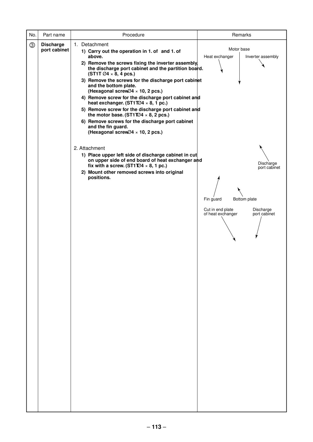
Detachment
113
No. Part name Procedure
114
115
116
Part name Procedure Remarks
117
118
Temporary Suspended State Inverter Assembly front
Compressor 1. Detachment
Temporary suspended state Inverter Assembly Ipdu
119
Fan motor 1. Detachment
120
Compressor terminal
121
122
Fan guard 1. Detachment
123
25, 26 22, 23 47, 55 33, 34 124
Exploded Views and Parts List
Location Model name Description RAV-SM2244 RAV-SM2804
125
126
Inverter Assembly
704
127
128
25, 26 22, 23 47, 55 33, 34
AT7 AT7Z AT7ZG
129
130
712
Location Model name
131
2244AT7ZG
2804AT7ZG
Check of Concentration Limit
Toshiba Carrier Corporation