2.5.3 Period Mode
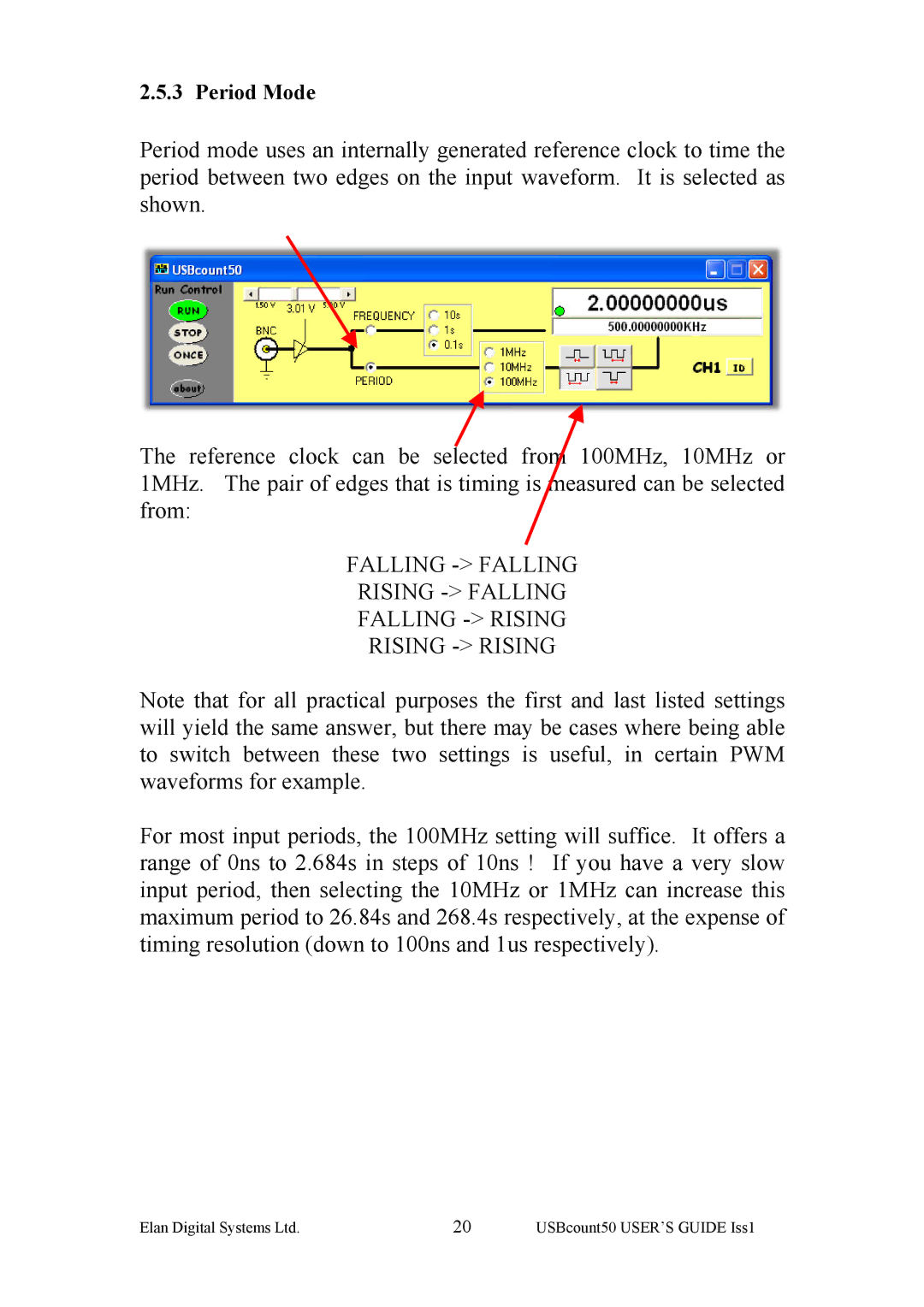
Period mode uses an internally generated reference clock to time the period between two edges on the input waveform. It is selected as shown.
The reference clock can be selected from 100MHz, 10MHz or 1MHz. The pair of edges that is timing is measured can be selected from:
FALLING -> FALLING
RISING -> FALLING
FALLING
RISING -> RISING
Note that for all practical purposes the first and last listed settings will yield the same answer, but there may be cases where being able to switch between these two settings is useful, in certain PWM waveforms for example.
For most input periods, the 100MHz setting will suffice. It offers a range of 0ns to 2.684s in steps of 10ns ! If you have a very slow input period, then selecting the 10MHz or 1MHz can increase this maximum period to 26.84s and 268.4s respectively, at the expense of timing resolution (down to 100ns and 1us respectively).
Elan Digital Systems Ltd. | 20 | USBcount50 USER’S GUIDE Iss1 |