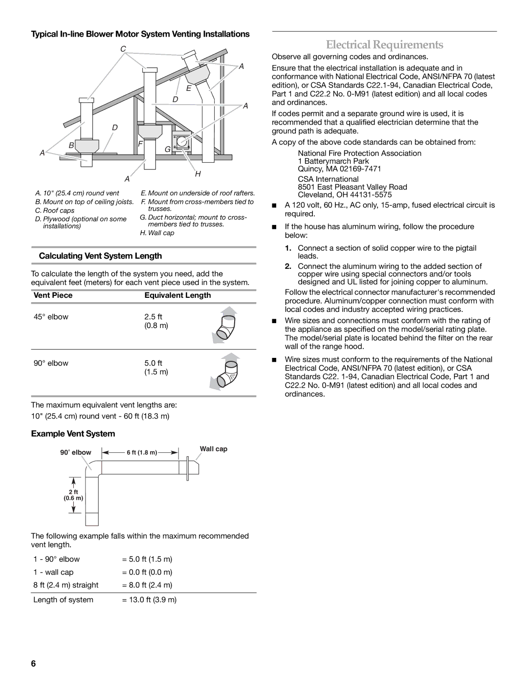
Typical In-line Blower Motor System Venting Installations
C
D
B
A
E
D
F![]()
G ![]()
A
A
Electrical Requirements
Observe all governing codes and ordinances.
Ensure that the electrical installation is adequate and in conformance with National Electrical Code, ANSI/NFPA 70 (latest edition), or CSA Standards
If codes permit and a separate ground wire is used, it is recommended that a qualified electrician determine that the ground path is adequate.
A copy of the above code standards can be obtained from:
National Fire Protection Association
| A | H |
|
| |
A. 10" (25.4 cm) round vent |
| E. Mount on underside of roof rafters. |
B. Mount on top of ceiling joists. F. Mount from
C. Roof caps | trusses. |
D. Plywood (optional on some | G. Duct horizontal; mount to cross- |
installations) | members tied to trusses. |
| H. Wall cap |
Calculating Vent System Length
To calculate the length of the system you need, add the equivalent feet (meters) for each vent piece used in the system.
Vent Piece | Equivalent Length |
45° elbow | 2.5 ft |
| (0.8 m) |
|
|
90° elbow | 5.0 ft |
| (1.5 m) |
The maximum equivalent vent lengths are:
10" (25.4 cm) round vent - 60 ft (18.3 m)
Example Vent System
90 elbow |
|
|
|
|
|
| Wall cap | ||
|
| 6 ft (1.8 m) |
|
| |||||
|
|
|
|
|
| ||||
|
|
|
|
|
|
|
|
|
|
|
|
|
|
|
|
|
|
|
|
|
|
|
|
|
|
|
|
|
|
2ft
(0.6 m)
The following example falls within the maximum recommended vent length.
1 | - 90° elbow | = 5.0 ft (1.5 m) |
1 | - wall cap | = 0.0 ft (0.0 m) |
8 ft (2.4 m) straight | = 8.0 ft (2.4 m) | |
|
| |
Length of system | = 13.0 ft (3.9 m) | |
1 Batterymarch Park
Quincy, MA
CSA International
8501 East Pleasant Valley Road
Cleveland, OH
■A 120 volt, 60 Hz., AC only,
■If the house has aluminum wiring, follow the procedure below:
1.Connect a section of solid copper wire to the pigtail leads.
2.Connect the aluminum wiring to the added section of copper wire using special connectors and/or tools designed and UL listed for joining copper to aluminum.
Follow the electrical connector manufacturer's recommended procedure. Aluminum/copper connection must conform with local codes and industry accepted wiring practices.
■Wire sizes and connections must conform with the rating of the appliance as specified on the model/serial rating plate. The model/serial plate is located behind the filter on the rear wall of the range hood.
■Wire sizes must conform to the requirements of the National Electrical Code, ANSI/NFPA 70 (latest edition), or CSA Standards C22.
6