When localcodes...
B.
Do Not Permit the use of Ihe flexible power supply cord equipped with the washer/dryer and
Permit copper power supply cable and
Permit connecting frame grounding conductor to Ihe neutral wire of the power supply cable:
Figure 9
1.Remove the power cord equipped with the washer/dryer as Instructed. See Panel F, “Toremove the power supply cord:’
2.Install copper power supply cable and stram relief.
3.Connect the neutral wire of the flexible armored or
4.Replace the terminal block cover.
When local codes...
Cn
Do Not Permit Ihe use of the flexible power supply cord equipped with the washer/dryer and
Permit copper power supply cable and
Do Not Permit connectmg frame grounding conductor to the neutral wire of the power supply cable:
Neutral | center |
(whim 0, ceme,) | terminal block screw |
Figure 10
1.Remove the power cord equipped with the washer/dryer as instructed. See “Toremove the power supply cord:’ Panel E
2.Install copper power supply cable and strain relief.
3.Remove the grounding wire (green) from the internal grounding connector and fasten under center,
4.Connect the neutral wire of the flexible armored or
5.Connect a separate copper grounding wire (No. 10 minimum). See “Toconnect a separate grounding wire:’ Panel F for detailed instructions.
6.Replace the terminal block cover.
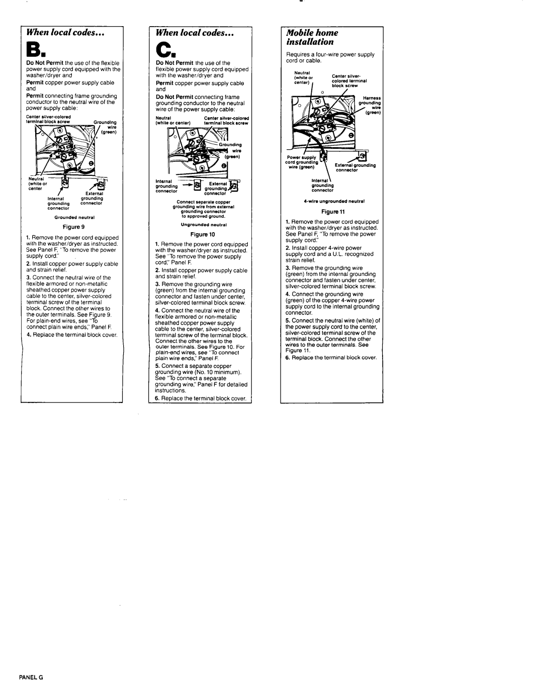
Mobile home installation
Requires a
Figure 11
1.Remove the power cord equipped with the washer/dryer as Instructed. See Panel F, “Toremove the power supply cord:’
2.Install copper
3.Remove the groundmg wire (green) from the inlernal grounding connector and fasten under center,
4.Connect the grounding wire (green) of the copper
5.Connect the neutral wire (white) of the power supply cord lo the center.
6.Replace the termmal block cover.