|
|
|
|
|
|
| Switch section |
|
|
|
|
|
|
| |
|
|
|
|
|
|
| |
|
|
|
|
|
|
|
|
|
|
|
|
| |||
| Item | Type | Label | Function | |||
|
|
|
|
|
| ||
| 11 |
| LED (red) | Not applicable | On/off status indicator for the BYPASS pushbutton. | ||
| 12 |
| LED meter | LEVEL | Signal level meter. The meter has +18dB, +12dB, | ||
|
|
|
|
|
|
| +6dB, 0dB, |
|
|
|
|
|
|
| output signal level (default). When the MTR I/P |
|
|
|
|
|
|
| pushbutton is on, the meter displays the input signal |
|
|
|
|
|
|
| level. |
|
|
|
|
|
|
|
|
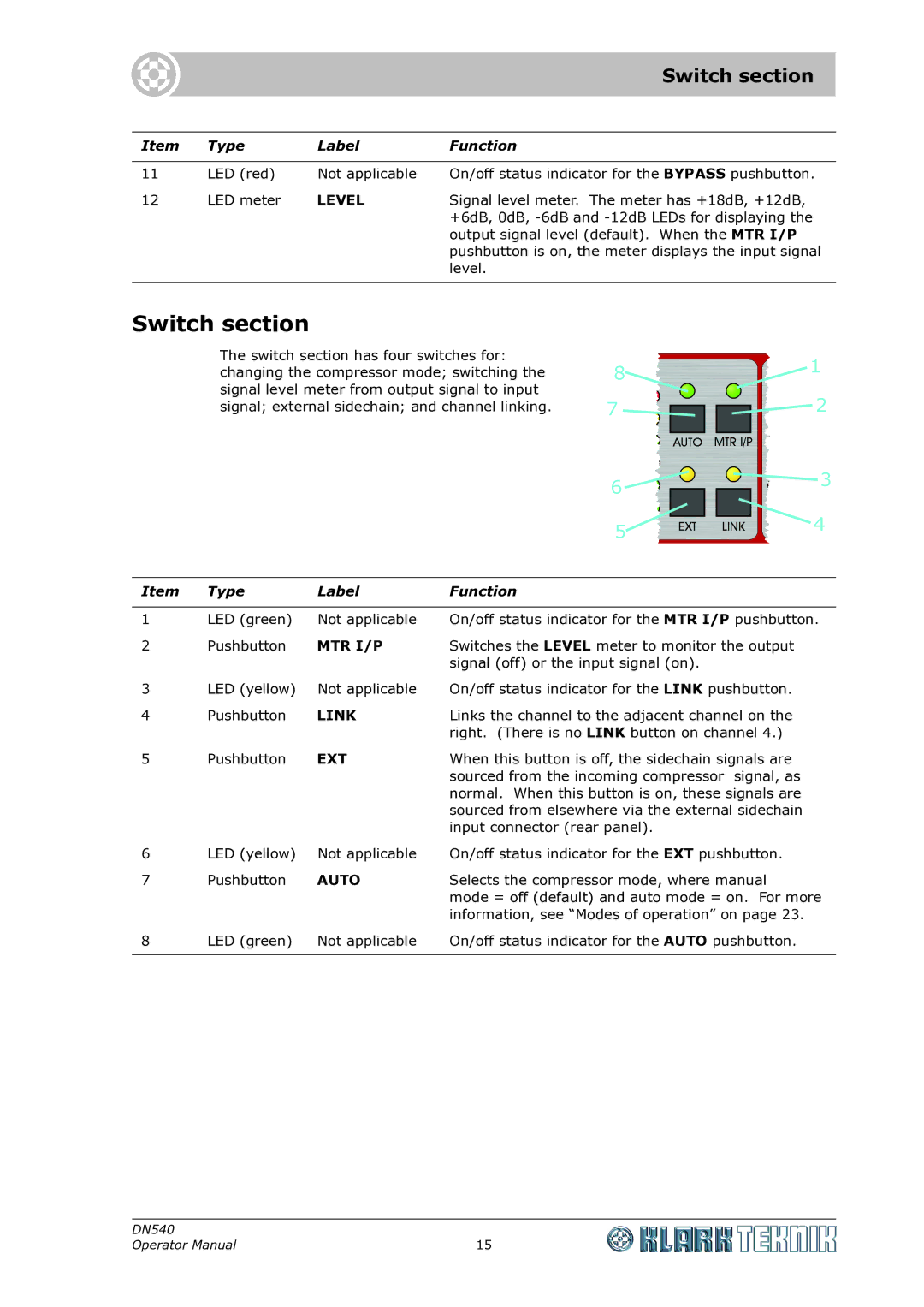
Switch section
The switch section has four switches for: changing the compressor mode; switching the signal level meter from output signal to input signal; external sidechain; and channel linking.
8 | 1 |
| |
7 | 2 |
6 | 3 |
| |
5 | 4 |
|
Item | Type | Label | Function |
|
|
|
|
1 | LED (green) | Not applicable | On/off status indicator for the MTR I/P pushbutton. |
2 | Pushbutton | MTR I/P | Switches the LEVEL meter to monitor the output |
|
|
| signal (off) or the input signal (on). |
3 | LED (yellow) | Not applicable | On/off status indicator for the LINK pushbutton. |
4 | Pushbutton | LINK | Links the channel to the adjacent channel on the |
|
|
| right. (There is no LINK button on channel 4.) |
5 | Pushbutton | EXT | When this button is off, the sidechain signals are |
|
|
| sourced from the incoming compressor signal, as |
|
|
| normal. When this button is on, these signals are |
|
|
| sourced from elsewhere via the external sidechain |
|
|
| input connector (rear panel). |
6 | LED (yellow) | Not applicable | On/off status indicator for the EXT pushbutton. |
7 | Pushbutton | AUTO | Selects the compressor mode, where manual |
|
|
| mode = off (default) and auto mode = on. For more |
|
|
| information, see “Modes of operation” on page 23. |
8 | LED (green) | Not applicable | On/off status indicator for the AUTO pushbutton. |
|
|
|
|
DN540 |
|
Operator Manual | 15 |