STAND ADJUSTMENT AND WALL MOUNTING
The speakers attach to their stands via a ball joint that allows them to be swiveled over a wide range. To adjust the angle,
Figure 2
Also on the underside of the base are three keyholes that enables the stand to function as a wall m o u n t . To install, follow the instructions below:
1 | . L o c ate the included wall mount template and bubble level and position on the wall in the desired |
| location. |
2 | . Mark the screw locations for the model you are installing. |
3 | . Screw #8 pan head wood screws (at least two inches) long into a wood stud or dry wall anchors |
| with the appropriateloadrat i n g . Leave the screw heads protruding from the wall surface |
| approximat e ly 1/4” and adjust as needed when hanging the speaker. |
4 | . Remove the center cover from the speaker’s base and |
| u n d e r s i d e . |
5 | . Loosen the four hex head screws on the speaker’s ball joint assembly and position the base |
| behind the speaker, pointing up the wall. |
6 | . G e n t ly tighten the four ball joint screws to secure the speaker’s position. You may need to |
|
|
7 | . Remove the logo from the speaker base by compressing its split post on the underside and rotate |
| it 180° for proper orientat i o n . |
8 | . Attach the supplied |
| speaker base. |
9 | . Hook the speaker base keyholes on the screw heads protruding from the wall. Adjust the height of |
| the screw heads for a snug fit. Do not over- t i g h t e n . |
1 0 | . If the speaker will be mounted over the location where the speaker wire emerges from the wall, |
| thread the wire through the hole in the speaker base’s |
| p l u g . |
1 1 | . Connect the speaker wire to the speakers binding posts. See “Speaker to A m p l i f i e r : Keeping it |
| S t r a i g h t . ” |
1 2 | . Fine tune the speaker’s angle and tighten the ball’s socket’s hex screws with the wrench. Do not |
| o v e |
1 3 | . Enjoy your favorite music and movies! |
C O N N E C T I O N S
N o t e : Proper connection of your speakers to your amplifier or receiver is vital to obtaining good sound q u a l i t y. Please follow these directions carefully. S l o p py connections can cause amplifier malfunction or damag e .
Klipsch Reference Series speakers are wired internally with Bandwidth Balanced® Monster Cab l e®. Bandwidth Balanced technology employs multiple gauges of
BUT FIRST: TYPES OF CONNECTO R S
B a re wire — Pull the two conductors apart for about an inch and strip approximat e ly 1 / 4 ” o f insulation from the end of each. (A wire stripper will simplify this, but you can use an ordinary pocket knife to cut around and through the insulation down to the wire.) Twist the strands of wire on each individual conductor tightly together. Loosen the nuts on a pair of binding posts until the holes through the metal posts are exposed, then insert the bare wire through the holes. Screw the nuts down
Pins — Many
Spade lugs — Some speaker cables are terminated with
OTHER TYPES OF SPECIALTY CONNECTORS ARE AVAILABLE TO FACILITATE HOOKING UP YOUR SPEAKERS. PLEASE CONSULT YOUR AUTHORIZED KLIPSCH DEALER FOR SUGGESTIONS AND FURTHER DETAILS.
SPEAKERS TO AMPLIFIER: KEEPING IT STRAIGHT
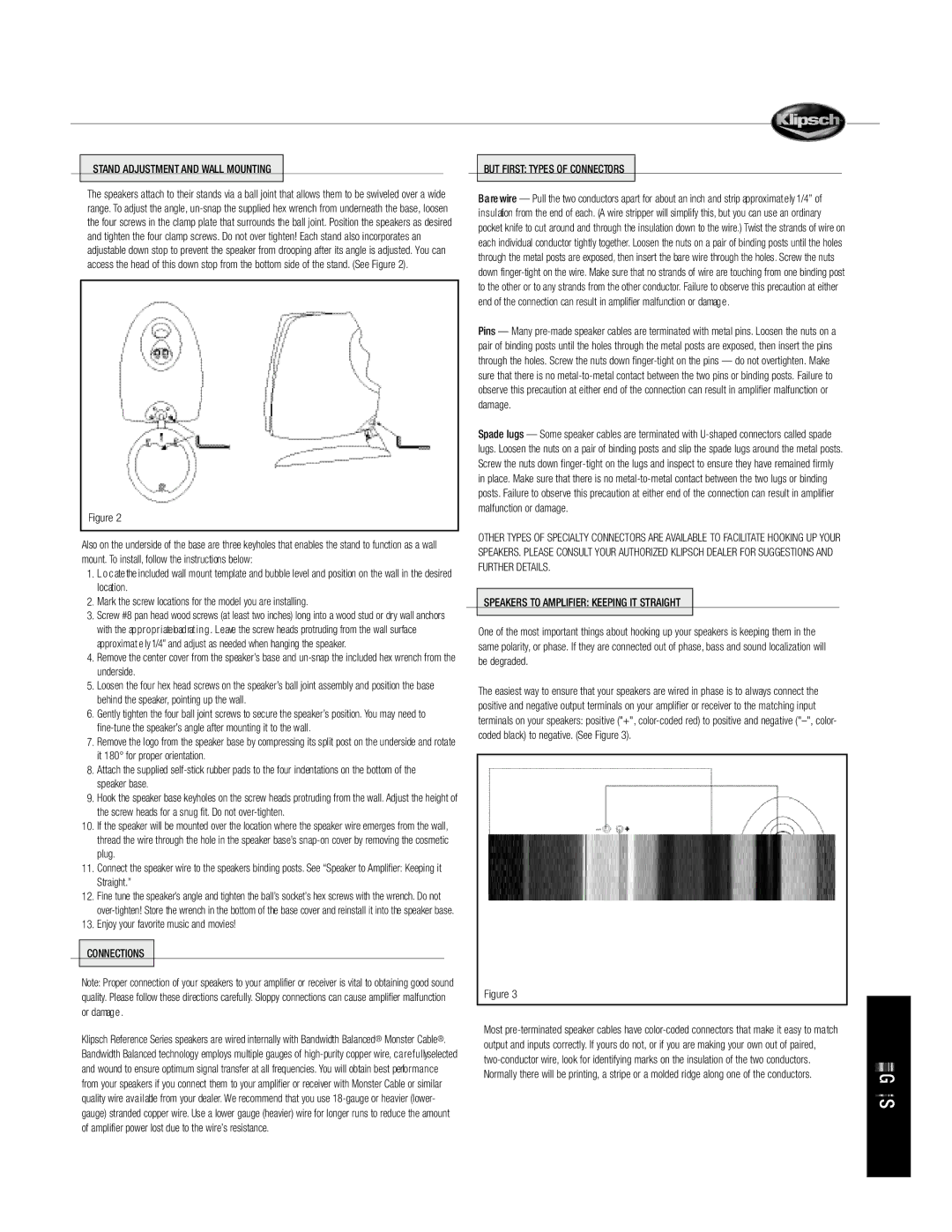
One of the most important things about hooking up your speakers is keeping them in the same polarity, or phase. If they are connected out of phase, bass and sound localization will be degraded.
The easiest way to ensure that your speakers are wired in phase is to always connect the positive and negative output terminals on your amplifier or receiver to the matching input terminals on your speakers: positive ("+",
Figure 3
Most