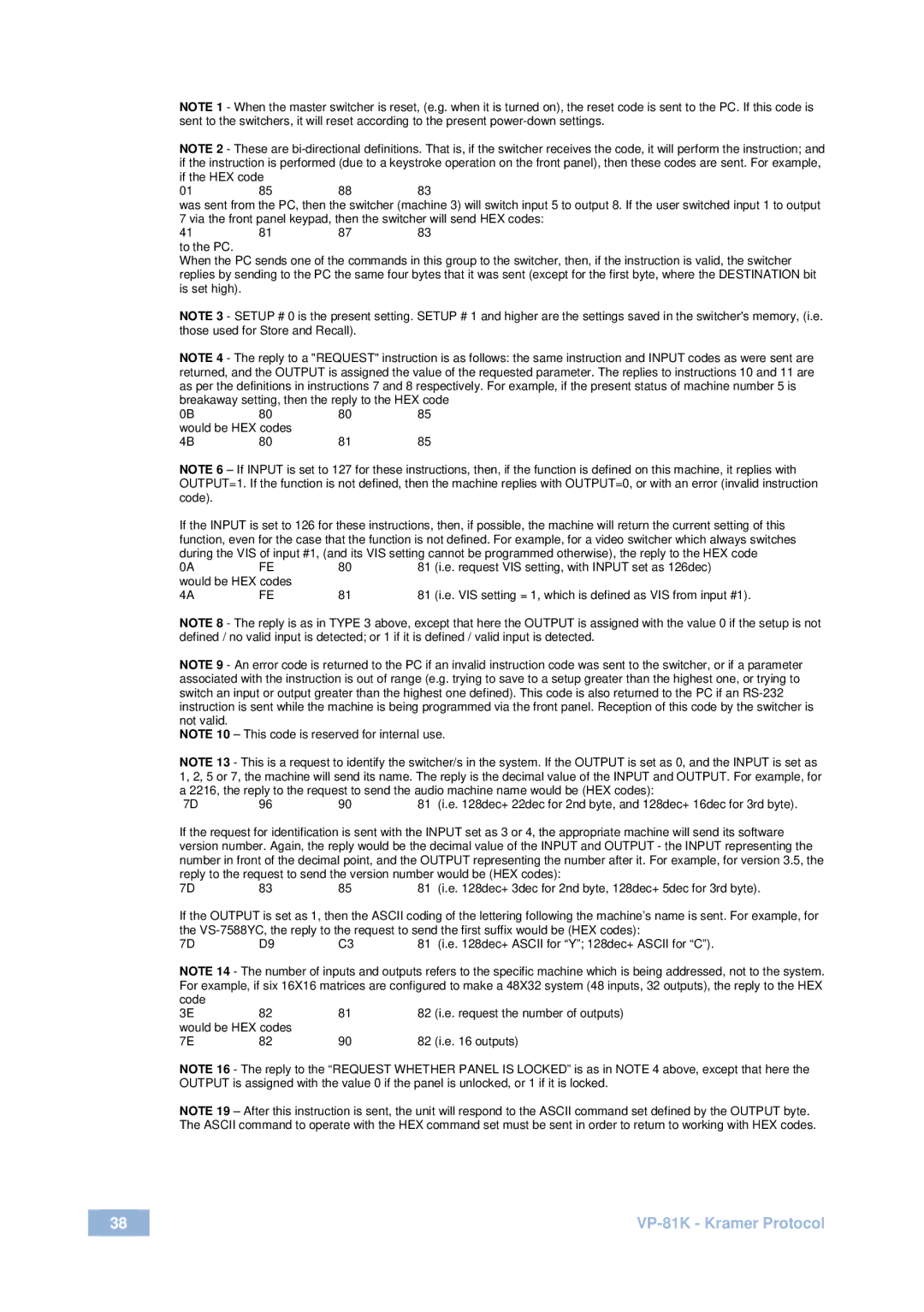
NOTE 1 - When the master switcher is reset, (e.g. when it is turned on), the reset code is sent to the PC. If this code is sent to the switchers, it will reset according to the present power-down settings.

NOTE 2 - These are bi-directional definitions. That is, if the switcher receives the code, it will perform the instruction; and if the instruction is performed (due to a keystroke operation on the front panel), then these codes are sent. For example,

if the HEX code


01

85

88

83

was sent from the PC, then the switcher (machine 3) will switch input 5 to output 8. If the user switched input 1 to output

7 via the front panel keypad, then the switcher will send HEX codes:

41 81 87 83 to the PC.

When the PC sends one of the commands in this group to the switcher, then, if the instruction is valid, the switcher replies by sending to the PC the same four bytes that it was sent (except for the first byte, where the DESTINATION bit is set high).

NOTE 3 - SETUP # 0 is the present setting. SETUP # 1 and higher are the settings saved in the switcher's memory, (i.e. those used for Store and Recall).

NOTE 4 - The reply to a "REQUEST" instruction is as follows: the same instruction and INPUT codes as were sent are returned, and the OUTPUT is assigned the value of the requested parameter. The replies to instructions 10 and 11 are as per the definitions in instructions 7 and 8 respectively. For example, if the present status of machine number 5 is breakaway setting, then the reply to the HEX code

0B

80

80

85

would be HEX codes


4B

80

81

85

NOTE 6 – If INPUT is set to 127 for these instructions, then, if the function is defined on this machine, it replies with OUTPUT=1. If the function is not defined, then the machine replies with OUTPUT=0, or with an error (invalid instruction code).

If the INPUT is set to 126 for these instructions, then, if possible, the machine will return the current setting of this function, even for the case that the function is not defined. For example, for a video switcher which always switches during the VIS of input #1, (and its VIS setting cannot be programmed otherwise), the reply to the HEX code

0A

FE

80

81

(i.e. request VIS setting, with INPUT set as 126dec)

would be HEX codes


4A

FE

81

81

(i.e. VIS setting = 1, which is defined as VIS from input #1).

NOTE 8 - The reply is as in TYPE 3 above, except that here the OUTPUT is assigned with the value 0 if the setup is not defined / no valid input is detected; or 1 if it is defined / valid input is detected.

NOTE 9 - An error code is returned to the PC if an invalid instruction code was sent to the switcher, or if a parameter associated with the instruction is out of range (e.g. trying to save to a setup greater than the highest one, or trying to switch an input or output greater than the highest one defined). This code is also returned to the PC if an RS-232 instruction is sent while the machine is being programmed via the front panel. Reception of this code by the switcher is not valid.

NOTE 10 – This code is reserved for internal use.

NOTE 13 - This is a request to identify the switcher/s in the system. If the OUTPUT is set as 0, and the INPUT is set as 1, 2, 5 or 7, the machine will send its name. The reply is the decimal value of the INPUT and OUTPUT. For example, for a 2216, the reply to the request to send the audio machine name would be (HEX codes):

7D 96 90 81 (i.e. 128dec+ 22dec for 2nd byte, and 128dec+ 16dec for 3rd byte).

If the request for identification is sent with the INPUT set as 3 or 4, the appropriate machine will send its software version number. Again, the reply would be the decimal value of the INPUT and OUTPUT - the INPUT representing the number in front of the decimal point, and the OUTPUT representing the number after it. For example, for version 3.5, the reply to the request to send the version number would be (HEX codes):

7D 83 85 81 (i.e. 128dec+ 3dec for 2nd byte, 128dec+ 5dec for 3rd byte).

If the OUTPUT is set as 1, then the ASCII coding of the lettering following the machine’s name is sent. For example, for the VS-7588YC, the reply to the request to send the first suffix would be (HEX codes):

7D D9 C3 81 (i.e. 128dec+ ASCII for “Y”; 128dec+ ASCII for “C”).

NOTE 14 - The number of inputs and outputs refers to the specific machine which is being addressed, not to the system. For example, if six 16X16 matrices are configured to make a 48X32 system (48 inputs, 32 outputs), the reply to the HEX

code


3E

82

81

82

(i.e. request the number of outputs)

would be HEX codes


7E

82

90

82

(i.e. 16 outputs)

NOTE 16 - The reply to the “REQUEST WHETHER PANEL IS LOCKED” is as in NOTE 4 above, except that here the OUTPUT is assigned with the value 0 if the panel is unlocked, or 1 if it is locked.

NOTE 19 – After this instruction is sent, the unit will respond to the ASCII command set defined by the OUTPUT byte. The ASCII command to operate with the HEX command set must be sent in order to return to working with HEX codes.

38

VP-81K - Kramer Protocol

Page 41
Image 41
Kramer Electronics VP-81 K user manual VP-81K Kramer Protocol

VP-81 K specifications

Kramer Electronics has established itself as a leading provider of innovative audio-visual solutions, and the VP-81 K is a noteworthy addition to their product lineup. This versatile presentation switcher is designed to accommodate a variety of audiovisual applications, making it ideal for classrooms, conference rooms, and professional events.

One of the standout features of the VP-81 K is its ability to handle multiple video formats. It supports both analog and digital inputs, including HDMI, VGA, and Composite video. This flexibility allows users to connect a wide range of devices, from laptops and projectors to higher-end sources and displays. The device seamlessly switches between input sources, ensuring a smooth presentation experience without interruption.

Another important characteristic of the VP-81 K is its built-in scaling technology. The device is equipped with a high-quality scaler that ensures output resolutions are optimized for a range of display formats. This means that regardless of the source resolution, the image quality remains crisp and clear, providing optimal viewing experiences for audiences.

The VP-81 K also boasts advanced audio capabilities. It allows for audio embedding and de-embedding, making it possible for users to manage both audio and video signals from a single device. This feature is particularly useful in settings where high-quality sound is essential, allowing for easier integration with external audio systems.

In terms of control, the VP-81 K is user-friendly. It provides multiple controlling options, including front-panel buttons, remote control, and RS-232 for integration with third-party systems. This flexibility ensures that users can easily manage their presentations, regardless of their technical expertise.

For enhanced security and performance, the VP-81 K features robust signal processing technology. It maintains signal integrity over long cable runs, ensuring that presentations remain professional and reliable. Additionally, the device is designed with durability in mind, utilizing high-quality components that withstand the rigors of frequent use.

Overall, the Kramer Electronics VP-81 K is a powerful and adaptable presentation switcher, equipped with essential features and cutting-edge technologies that cater to modern audiovisual needs. Whether in educational settings or corporate environments, its capabilities are sure to elevate any presentation experience.