9 Protocol 2000

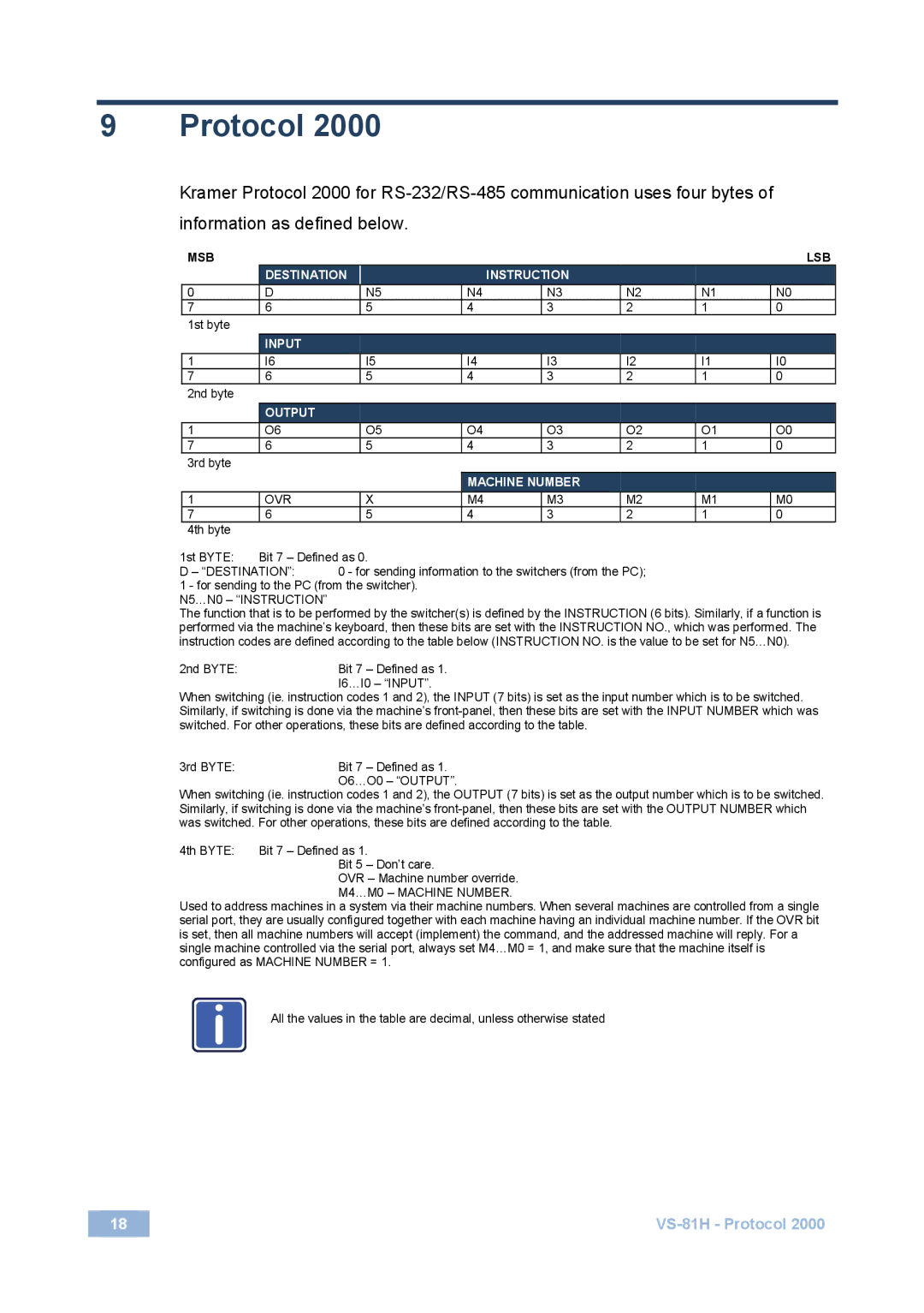
Kramer Protocol 2000 for RS-232/RS-485 communication uses four bytes of information as defined below.

MSB


LSB


DESTINATION


INSTRUCTION


0

D


N5

N4


N3

N2

N1

N0

7

6


5

4


3

2

1

0

1st byte


INPUT


1

I6


I5

I4


I3

I2

I1

I0

7

6


5

4


3

2

1

0

2nd byte


OUTPUT


1

O6


O5

O4


O3

O2

O1

O0

7

6


5

4


3

2

1

0

3rd byte


MACHINE NUMBER


1

OVR


X

M4


M3

M2

M1

M0

7

6


5

4


3

2

1

0

4th byte


1st BYTE:

Bit 7 – Defined as 0.


D – “DESTINATION”:

0 - for sending information to the switchers (from the PC);


1 - for sending to the PC (from the switcher).


N5…N0 – “INSTRUCTION”

The function that is to be performed by the switcher(s) is defined by the INSTRUCTION (6 bits). Similarly, if a function is performed via the machine’s keyboard, then these bits are set with the INSTRUCTION NO., which was performed. The instruction codes are defined according to the table below (INSTRUCTION NO. is the value to be set for N5…N0).

2nd BYTE:Bit 7 – Defined as 1. I6…I0 – “INPUT”.

When switching (ie. instruction codes 1 and 2), the INPUT (7 bits) is set as the input number which is to be switched. Similarly, if switching is done via the machine’s front-panel, then these bits are set with the INPUT NUMBER which was switched. For other operations, these bits are defined according to the table.

3rd BYTE:Bit 7 – Defined as 1. O6…O0 – “OUTPUT”.

When switching (ie. instruction codes 1 and 2), the OUTPUT (7 bits) is set as the output number which is to be switched. Similarly, if switching is done via the machine’s front-panel, then these bits are set with the OUTPUT NUMBER which was switched. For other operations, these bits are defined according to the table.

4th BYTE:

Bit 7 – Defined as 1.


Bit 5 – Don’t care.


OVR – Machine number override.


M4…M0 – MACHINE NUMBER.

Used to address machines in a system via their machine numbers. When several machines are controlled from a single serial port, they are usually configured together with each machine having an individual machine number. If the OVR bit is set, then all machine numbers will accept (implement) the command, and the addressed machine will reply. For a single machine controlled via the serial port, always set M4…M0 = 1, and make sure that the machine itself is configured as MACHINE NUMBER = 1.

i

All the values in the table are decimal, unless otherwise stated


18

VS-81H - Protocol 2000

Page 21
Image 21
Kramer Electronics VS-81H user manual Protocol, Machine Number

VS-81H specifications

The Kramer Electronics VS-81H is a sophisticated yet user-friendly 8x1 HDMI switcher designed for various audio-visual applications, making it an excellent choice for conference rooms, classrooms, and home theater setups. This device allows seamless switching between multiple HDMI sources, providing an efficient solution for users who require a reliable method to manage multiple HDMI devices.

One of the main features of the VS-81H is its ability to handle high-definition video resolutions of up to 4K at 60Hz, offering stunning picture clarity and detail. The switcher supports Deep Color, ensuring vibrant colors and a more immersive viewing experience. This makes it especially suitable for applications where image quality is paramount, such as presentations and film screenings.

The VS-81H incorporates advanced technology, including EDID PassThru, which automatically manages the communication between the HDMI source and display. This feature simplifies the connection process and ensures compatibility between devices, eliminating issues often encountered with different HDMI standards. Additionally, the switcher is equipped with a powerful 3D video processing capability, further enhancing the versatility of the unit for different media types.

Another notable characteristic of the Kramer VS-81H is its user-friendly interface. The device can be controlled via front panel buttons, remote control, or RS-232 interface. This flexibility provides users with various control options, enhancing ease of operation in various environments. The compact design of the VS-81H also allows for easy integration into existing setups, making it a practical choice for users concerned about space.

The switcher also features automatic switching capabilities, detecting the active source and routing it to the output automatically. This functionality streamlines the switching process, ensuring that users don’t have to manually toggle inputs during presentations or viewing sessions.

In terms of connectivity, the VS-81H provides audio support by embedding audio signals with video, enabling a clean and straightforward setup. This feature is crucial for users wishing to maintain audio-video sync without additional cabling or external audio devices.

Overall, the Kramer Electronics VS-81H combines robust performance, high-quality video support, and user-friendly features, making it an exceptional choice for anyone looking to enhance their audio-visual experience. Its reliable operation, versatility, and ease of use position it as a top contender in the market for HDMI switchers.