KST100 specifications
Krell Industries is renowned for its commitment to high-end audio components, and the KST100 amplifier exemplifies this dedication to quality and performance. Designed for audiophiles who seek an immersive listening experience, the KST100 encompasses a blend of advanced technologies and superior engineering.At the heart of the KST100 is its Class A/B topology, which ensures that the amplifier delivers an impressive balance of efficiency and power. This design not only maximizes audio fidelity but also provides a warm, rich sound that is ideal for both dynamic peaks and subtle nuances in music. With a power output of up to 100 watts per channel into 8 ohms, the KST100 is versatile enough to drive a variety of speaker types, making it suitable for different audio setups.
One of the standout features of the KST100 is its unique Krell Current Mode technology. This innovative approach prioritizes the direct manipulation of current as opposed to voltage, allowing the amplifier to respond more rapidly to transient signals. The result is cleaner, more dynamic sound reproduction that remains faithful to the original recording.
Additionally, the KST100 incorporates a fully differential circuit design, which helps to reduce noise and distortion significantly. This design feature ensures that the audio signal remains untainted throughout the signal path, resulting in a clearer and more detailed soundstage. The amplifier also boasts an oversized transformer and extensive power supply capabilities, which further contribute to its impressive performance levels.
The KST100 is equipped with a minimalist front panel and intuitive layout, embodying Krell's philosophy of marrying functionality with elegance. Its robust chassis is engineered to minimize vibration and electromagnetic interference, crucial in preserving the integrity of the audio signal.
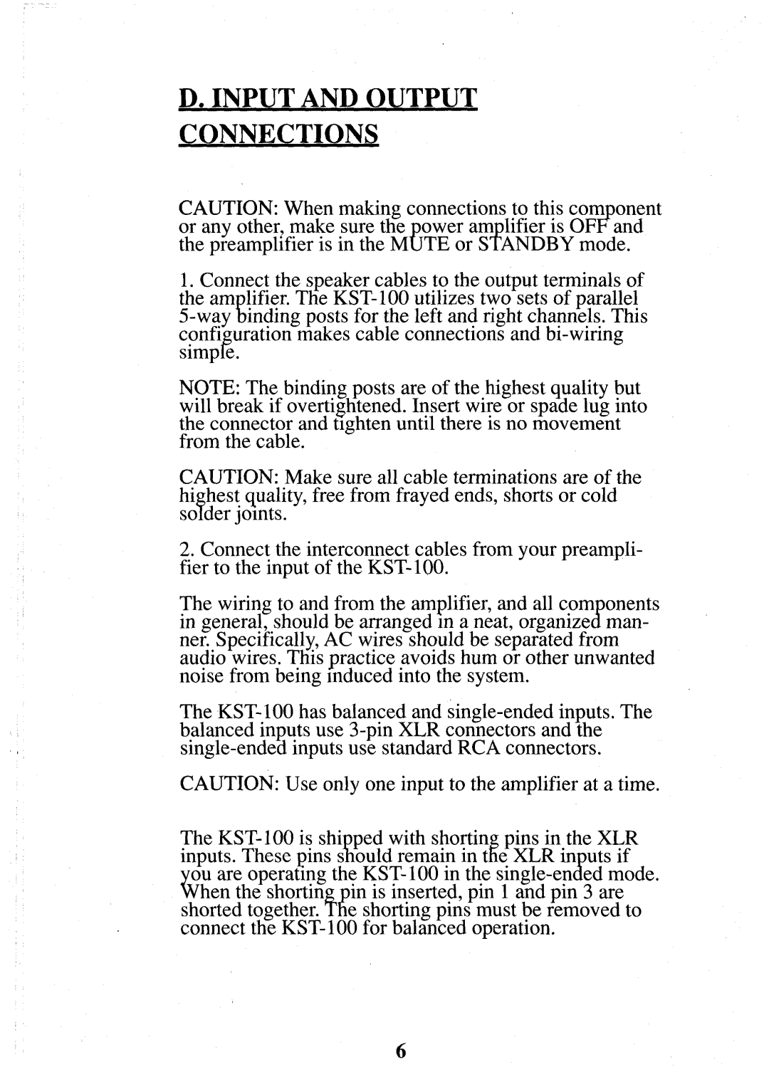
Connectivity options are plentiful, with the KST100 featuring balanced XLR and unbalanced RCA inputs, facilitating seamless integration with various sources. In addition, the amplifier is designed with durability in mind, constructed from high-quality materials that ensure longevity and reliable performance over time.
In summary, the Krell Industries KST100 stands out as a high-performance amplifier that captures the essence of audio excellence. With its innovative design, sophisticated technology, and user-friendly features, it caters to the needs of serious music lovers, making it a prime choice for those looking to elevate their audio experience.

