1.2 Connector and LEDs
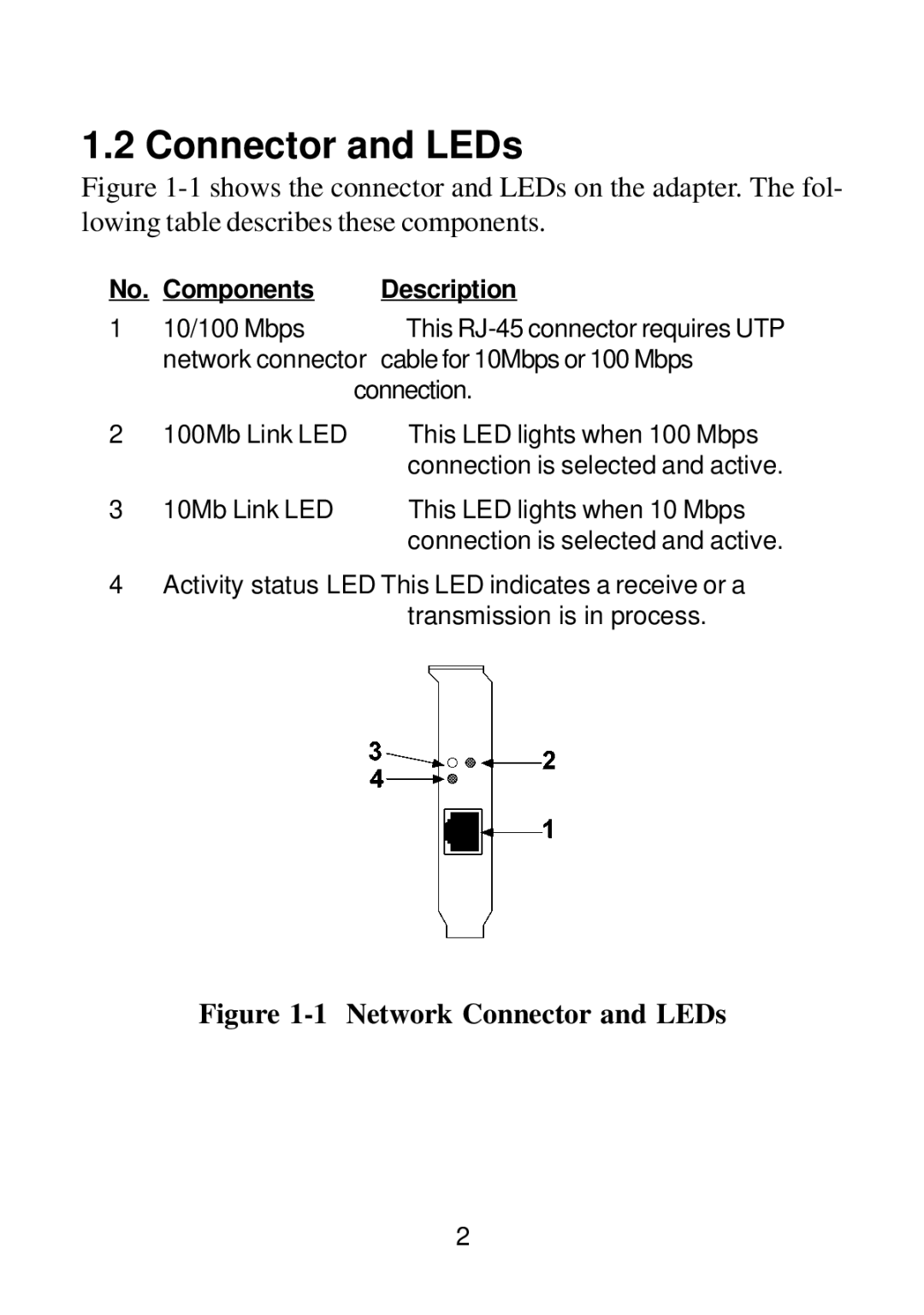
Figure 1-1 shows the connector and LEDs on the adapter. The fol- lowing table describes these components.
No. | Components | Description |
1 | 10/100 Mbps | This |
| network connector | cable for 10Mbps or 100 Mbps |
| connection. | |
2 | 100Mb Link LED | This LED lights when 100 Mbps |
|
| connection is selected and active. |
3 | 10Mb Link LED | This LED lights when 10 Mbps |
|
| connection is selected and active. |
4Activity status LED This LED indicates a receive or a transmission is in process.
Figure 1-1 Network Connector and LEDs
2
