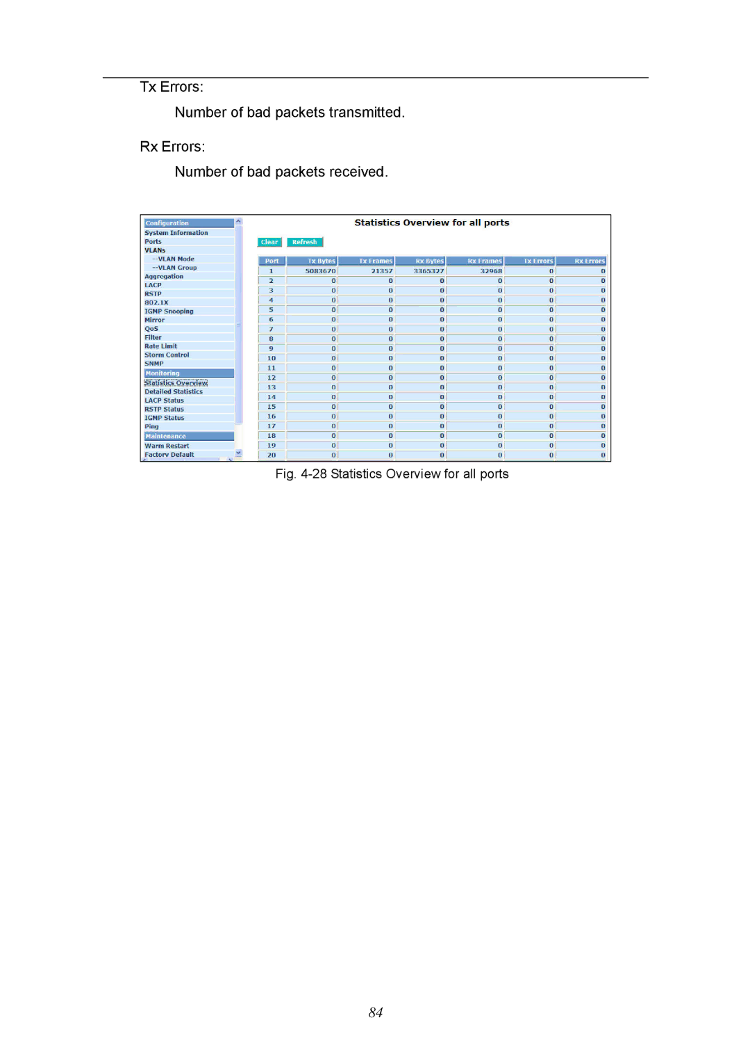
Manuals
/
KTI Networks
/
Computer Equipment
/
Switch
KTI Networks
KGS-2404 manual Tx Errors Number of bad packets transmitted Rx Errors
Models:
KGS-2404
1
90
113
113
Download
113 pages
39.13 Kb
87
88
89
90
91
92
93
94
<
>
Specification
Install
Dimension
Maintenance
Configuration
Default gateway
Takes the Delay Time into Account
DSCP Setting
Checklist
Weight
Page 90
Image 90
Tx Errors:
Number of bad packets transmitted.
Rx Errors:
Number of bad packets received.
Fig.
4-28
Statistics Overview for all ports
84
Page 89
Page 91
Page 90
Image 90
Page 89
Page 91
Contents
KGS-2404
Web Smart 24-Port Gigabit Ethernet Switch User’s Manual
DOC.080711
Page
Web Smart 24-Port Gigabit Ethernet Switch Users Manual
Release
Table of Contents
4-4. Maintenance
1.02
Revision History
Electronic Emission Notices
06/28/2007
About this user’s manual
Overview of this user’s manual
1-1. Overview of 24-Port GbE Web Smart Switch
Key Features in the Device
1. Introduction
Hardware
1-2. Checklist
1-3. Features
Management
Supports to send the trap event while monitored events happened
Supports user management and limits one user to login
Supports 802.1Q VLAN
Supports on-line plug/unplug SFP modules
1-4. View of 24-Port GbE Web Smart Switch
1-4-1. User Interfaces on the Front Panel Button, LEDs and Plugs
System LED
LED Indicators
1-4-2. User Interfaces on the Rear Panel
10/100/1000Ethernet TP Port 1 to 24 LED
1-5. View of the Optional Modules
2-1-1. Hardware and Cable Installation
2. Installation
2-1. Starting 24-Port GbE Web Smart Switch Up
Connecting the SFP Module to the Chassis
2-1-2. Cabling Requirements
TP Port and Cable Installation
Power On
Firmware Loading
2-1-2-1. Cabling Requirements for TP Ports
2-1-2-2. Cabling Requirements for 1000SX/LX SFP Module
1000Base-X TP, Fiber
2-1-2-3. Switch Cascading in Topology
Takes the Delay Time into Account
100Base-TX TP
Case2a Port-based VLAN See Fig.2-3
Case 2b Port-based VLAN See Fig.2-4
Page
Managing 24-Port GbE Web Smart Switch through Ethernet Port
2-1-3-1. Management through Ethernet Port
2-1-4. IP Address Assignment
Class A
25 bits All 0s = 128.1.2.128 All 1s=
Network
Subnet
10000000.00000001.00000010.1
Prefix LengthNo. of IP matchedNo. of Addressable IP
Default gateway
2-2. Typical Applications
Fig. 2-11 Peer-to-peer Network Connection
Fig. 2-12 Office Network Connection
3. Basic Concept and Management
3-1. What’s the Ethernet
Physical Layer
Data Link Layer
IEEE 802.2 LLC IEEE802.3 CSMA/CD MAC
IEEE 802.3 PLS IEEE MAU Coaxial/STP/UTP
0xAAAA
3-2. Media Access Control MAC
1st byte
For example 0x0800 IP datagram 0x0806 ARP 0x0835 RARP
0x8137 IPX datagram 0x86DD IPv6
The MAC sub-layer has two primary jobs to do
64 bytes
Fig. 3-4 Gigabit Ethernet Frame
Parameter value/LAN Max. collision domain DTE to DTE
BurstLimit
Table 3-4 Ethernet parameters for half duplex mode
3-3. Flow Control
Frame Reception
For a received frame, the MAC will check
Bits Bit Bits
3-4. How does a switch work?
Extended Distance Limitations
How does a switch operate?
MAC address table
Mac address aging
FCFS First Come First Service Strictly Priority All High before Low
Weighted Round Robin
Transmission schedule
3-5. Virtual LAN
Page
Fig.3-9 Tag Format
Untagged frame An Ethernet frame carries no VLAN tag information
VLAN-tagged frame
Priority-tagged frame
VLAN Identifier
Independent VLAN Learning IVL
Ingress Rule
Egress Rule
Shared VLAN Learning SVL
Network Address
Name
Port Members
Name
3-6. Link Aggregation
Terminology Link Aggregation
IP Address Subnet Mask Default Gateway Password
4. Operation of Web-based Management
4-1. Web Management Home Overview
The Information of Page Layout
4-2. Configuration
Function description
4-2-1. System Configuration
Function name
Parameter description
Show the active gateway of this switch. DHCP Server
Show the active IP address of this switch. Active Subnet Mask
Show the active subnet mask of this switch. Active Gateway
Show the IP address of the DHCP server. Default Lease Time Left
Show the management VLAN number. Password
Default 255.255.255.0 Fallback Gateway
Default 192.168.1.254 Management VLAN
Default admin Inactivity Timeoutsecs
NWay
4-2-2. Port Configuration
Media type
Speed
Function description
4-2-3. VLAN Mode Configuration
Function name
Parameter description
Tag-based
Function description
4-2-4. VLAN Group Configuration
Function name
Parameter description
Delete Group
Fig. 4-9 Port-Based VLAN Configuration
Add Group
Fig. 4-8 Add or Remove VLAN Member
Page
Function description
4-2-5. Aggregation
Function name
Parameter description
Function description
4-2-6. LACP
Function name
Parameter description
Function description
4-2-7. RSTP
Function name
Parameter description
Function description
continue Fig. 4-12 RSTP Configuration
Function name
Parameter description
4-2-8
Supplicant
Page
Page
Port Control
Authentication
Port Mode
Port Status
Mode Enable or disable 802.1X function RADIUS IP
Function description
Force Reinitialize for all ports in at once
Function description
Function name
802.1x Parameters
Parameter description
Function name
4-2-9 IGMP Snooping
Fig. 4-19 IGMP Configuration
Function description
4-2-10. Mirror Configuration
Function name
Parameter description
4-2-11. QoSQuality of Service Configuration
Fig. 4-21 QoS Configuration
Function name
Function name
Function description
DSCP Setting
Function name
Parameter description
Function description
4-2-12 Filter
Function name
Parameter description
Fig. 4-24 Filter Configuration
Default enable
DHCP Server Allowed
Function description
4-2-13 Rate Limit
Function name
Parameter description
Function description
4-2-14 Storm Control
Function name
Parameter description
Multicast Rate
Flooded unicast Rate
Function name
4-2-15 SNMP
Parameters description
Function description
Default community name for Trap public
Default community name for Get public
Default community name for Set private
Fig. 4-27 SNMP Configuration
Function name
4-3. Monitoring
4-3-1. Statistics Overview
Function description
Tx Errors Number of bad packets transmitted Rx Errors
Number of bad packets received
Fig. 4-28 Statistics Overview for all ports
Function description
4-3-2. Detailed Statistics
Function name
Parameter description
Number of 1024-maxlength-byte frames in good and bad packets received
Tx Error Packets
Show the counting number of the received error packets. Rx 64 Bytes
Tx 64 Bytes
Number of short frames 64 bytes with invalid CRC. Rx Jabber
Function description
4-3-3. LACP Status
Function name
Parameter description
Function description
4-3-4. RSTP Status
Function name
Parameter description
Fig. 4-31 RSTP Status
Function description
4-3-5. IGMP Status
Function name
Parameter description
Function description
4-3-6. Ping Status
Function name
Parameter description
Target IP address Show the active target IP address. Status
Show the received replies number of times. Request timeouts
Show the timeout of request. Average Response times In ms
Show the result of the ping status. Received replies
Maintenance Warm Restart Factory Default Software Upgrade
4-4. Maintenance
There are five functions contained in the maintenance function
Configuration File Transfer Logout
4-4-1. Warm Restart
Function name
Function description
4-4-2. Factory Default
Function name
Function description
Fig. 4-36 Software Upgrade
4-4-3. Software Upgrade
Software Upgrade
Function name
4-4-4. Configuration File Transfer
Function description
Function name
Function description
4-4-5. Logout
Function name
Parameter description
5. Maintenance
5-1. Resolving No Link Condition
5-2. Q&A
Appendix A Technical Specifications
Features
Connector
Hardware Specifications
Configuration
Network Interface
Ambient Temperature
Diagnostic LED
Power Requirement
Dimensions
Quality of Service QoS
Management Software Specifications
System Configuration
VLAN Function
Appendix B MIB Specifications