KTI Networks KGS-2404 manual 1st byte

Models: KGS-2404

1 113
Download 113 pages 39.13 Kb
Page 33
Image 33
1st byte

Bit 47


bit 0

1st byte

2nd byte

3rd byte

4th byte

5th byte

6th byte


OUI code


Serial number


Table 3-3 Ethernet MAC address

The first bit of the first byte in the Destination address (DA) determines the address to be a Unicast (0) or Multicast frame (1), known as I/G bit indicating individual (0) or group (1). So the 48-bit address space is divided into two portions, Unicast and Multicast. The second bit is for global-unique (0) or locally-unique address. The former is assigned by the device manufacturer, and the later is usually assigned by the administrator. In practice, global-unique addresses are always applied.

A unicast address is identified with a single network interface. With this nature of MAC address, a frame transmitted can exactly be received by the target an interface the destination MAC points to.

A multicast address is identified with a group of network devices or network interfaces. In Ethernet, a many-to-many connectivity in the LANs is provided. It provides a mean to send a frame to many network devices at a time. When all bit of DA is 1s, it is a broadcast, which means all network device except the sender itself can receive the frame and response.

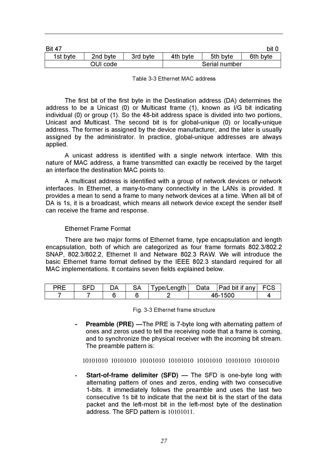
Ethernet Frame Format

There are two major forms of Ethernet frame, type encapsulation and length encapsulation, both of which are categorized as four frame formats 802.3/802.2 SNAP, 802.3/802.2, Ethernet II and Netware 802.3 RAW. We will introduce the basic Ethernet frame format defined by the IEEE 802.3 standard required for all MAC implementations. It contains seven fields explained below.

PRE

SFD

DA

SA

Type/Length

Data

Pad bit if any

FCS

7

7

6

6

2

46

-1500

4

Fig. 3-3 Ethernet frame structure

-Preamble (PRE) —The PRE is 7-byte long with alternating pattern of ones and zeros used to tell the receiving node that a frame is coming, and to synchronize the physical receiver with the incoming bit stream. The preamble pattern is:

10101010 10101010 10101010 10101010 10101010 10101010 10101010

-Start-of-frame delimiter (SFD) — The SFD is one-byte long with alternating pattern of ones and zeros, ending with two consecutive 1-bits. It immediately follows the preamble and uses the last two consecutive 1s bit to indicate that the next bit is the start of the data packet and the left-most bit in the left-most byte of the destination address. The SFD pattern is 10101011.

27

Page 33
Image 33
KTI Networks KGS-2404 manual 1st byte