Manuals
/
KTI Networks
/
Computer Equipment
/
Switch
KTI Networks
KGS-2404
manual
Peer-to-peer Network Connection
Models:
KGS-2404
1
28
113
113
Download
113 pages
39.13 Kb
25
26
27
28
29
30
31
32
Install
No Vlan Configuration Diagram
Factory Default
LED Indicators
Login
Dimension
Maintenance
System Configuration
Media Access Control MAC
Dscp Setting
Page 28
Image 28
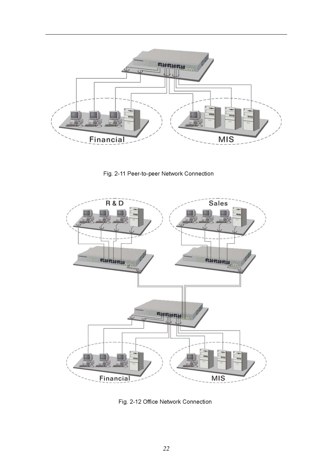
Fig.
2-11
Peer-to-peer
Network Connection
Fig.
2-12
Office Network Connection
22
Page 27
Page 29
Page 28
Image 28
Page 27
Page 29
Contents
KGS-2404
Page
Release
Table of Contents
100
06/28/2007 03/13/2007 02/10/2007
Federal Communications Commission FCC Statement
About this user’s manual
Key Features in the Device
Overview of 24-Port GbE Web Smart Switch
Vlan
Checklist
Features
Hardware
Management
Page
View of 24-Port GbE Web Smart Switch
User Interfaces on the Front Panel Button, LEDs and Plugs
LED Indicators
User Interfaces on the Rear Panel
System LED
10/100/1000Ethernet TP Port 1 to 24 LED
View of the Optional Modules
Front View of 1000Base-SX/LX LC, SFP Fiber Transceiver
Hardware and Cable Installation
Starting 24-Port GbE Web Smart Switch Up
Connecting the SFP Module to the Chassis
TP Port and Cable Installation
Power On
Cabling Requirements
Firmware Loading
Cabling Requirements for TP Ports
Cabling Requirements for 1000SX/LX SFP Module
1000Base-X TP, Fiber 100Base-TX TP 100Base-FX Fiber
Typical Network Topology in Deployment
No Vlan Configuration Diagram
Case 2b Port-based Vlan See -4
Page
Managing 24-Port GbE Web Smart Switch through Ethernet Port
Management through Ethernet Port
Login Screen for Web
IP Address Assignment
110
10000000.00000001.00000010.1
Prefix Length No. of IP matched No. of Addressable IP
Page
Typical Applications
10 Network Connection between Remote Site and Central Site
11 Peer-to-peer Network Connection
Basic Concept Management
What’s the Ethernet
IEEE802.3 CSMA/CD MAC
STP Bpdu
Snap
ARP
Media Access Control MAC
SAP Format
PRE SFD
FCS
Page
How does a MAC work?
Bytes
DTE
Flow Control
Page
Bits
How does a switch work?
Collision Domain
Page
Page
Virtual LAN
Page
CFI
Tag Format
Page
Page
VID
Link Aggregation
10 Example of Link Aggregation Application
Operation of Web-based Management
Web Management Home Overview
Information of Page Layout
Lacp Rstp
Snmp
System Configuration
Function description
Page
Page
Port Configuration
ON/OFF
Vlan Mode Configuration
Port Configuration
Select Vlan Mode
Vlan Group Configuration
VID
Add or Remove Vlan Member
Page
10 Aggregation/Trunking Configuration
Aggregation
11 Lacp Port Configuration
Lacp
Rstp
Rstp Port Configuration
Page
Page
Page
Port Mode Port Control Authentication Port Status
Radius IP
16 802.1X Configuration
802.1x Parameters
Igmp Snooping
Vlan ID
Mirror Configuration
20 Mirror ports configuration
QoSQuality of Service Configuration
21 QoS Configuration
QoS Configuration
Dscp Setting
Filter
Dhcp
24 Filter Configuration
25 Rate Limit Configuration
Rate Limit
26 Storm Control Configuration
Storm Control
Page
Snmp
Parameters description
27 Snmp Configuration
Monitoring
Statistics Overview
28 Statistics Overview for all ports
Detailed Statistics
Page
29 Detailed Statistics for each port
Lacp Status
30 Lacp Status
Rstp Status
31 Rstp Status
Igmp Status
Ping Status
32 Igmp Status
33 Ping
Maintenance
Warm Restart
34 Warm Restart
Factory Default
Software Upgrade
36 Software Upgrade
Configuration File Transfer
Function description
Logout
Resolving No Link Condition
Q&A
Appendix a Technical Specifications
ƒ Network Interface
SFP
ƒ MAC Address and Self-learning 8K MAC address
ƒ Cable and Maximum Length
ƒ Diagnostic LED
ƒ Power Requirement
Ambient Temperature
Dimensions
Management Software Specifications
PRIVATE-GESM-SW24L-MIB Definitions = Begin Imports
From RFC1213-MIB
From RFC1155-SMI
OBJECT-TYPE
Top
Page
Image
Contents