Land Pride
Assembly Instructions
Assembly of CVT Pulley and Belt
Refer to Figure 4:
IMPORTANT: Pulley flanges will bend and nick easily if handled roughly. Always handle pulleys gently to prevent damage.
1.Make a dry run by installing driven pulley (#18) onto
2.Make certain shims in step 3e on page 4 are still on the engine shaft.
3.Apply
4.Slide drive pulley (#17) onto engine drive shaft and hang belt (#16) on drive pulley (#17).
5.Apply
6.Install belt (#16) on driven pulley (#18) and slide pulley onto
7.Push both pulleys with installed belt back until they stop. Recheck belt alignment.
8.Secure drive pulley (#17) with
9.Secure driven pulley (#18) with
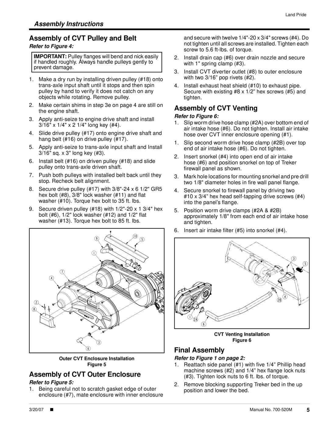
Outer CVT Enclosure Installation
Figure 5
Assembly of CVT Outer Enclosure
Refer to Figure 5:
1.Being careful not to scratch gasket edge of outer enclosure (#7), mate enclosure with inner enclosure
and secure with twelve
2.Install drain cap (#6) over drain nozzle and secure with 1" spring clamp (#3).
3.Install CVT diverter outlet (#8) to outer enclosure with two 3/16” pop rivets (#2).
4.Install exhaust heat shield (#10) to exhaust pipe. Secure with existing #8 x 1/2” hex screws (#5) and tighten.
Assembly of CVT Venting
Refer to Figure 6:
1.Slip worm drive hose clamp (#2A) over bottom end of air intake hose (#6). Do not tighten. Install air intake hose over CVT inner enclosure opening (#1).
1.Slip second worm drive hose clamp (#2B) over top end of air intake hose (#6). Do not tighten.
2.Insert snorkel (#4) into open end of air intake hose (#6) and position snorkel on top of Treker firewall panel as shown.
3.Mark hole locations for mounting snorkel and pre drill two 1/8" diameter holes in fire wall panel flange.
4.Secure snorkel to firewall panel by driving two #10 x 3/4” hex head
5.Position worm drive clamps (#2A & #2B) approximately 1/8" from each end of air intake hose and tighten.
6.Insert air intake filter (#5) into snorkel (#4).
CVT Venting Installation
Figure 6
Final Assembly
Refer to Figure 1 on page 2:
1.Reattach side panel (#1) with five 1/4” Phillip head machine screws (#2) and 1/4” hex flange lock nuts (#3). Tighten lock nuts to 6 ft. lbs. of torque.
2.Remove blocking supporting Treker bed in the up position and lower the bed.
3/20/07 ■ | Manual No. | 5 |