ASSEMBLY
Assembly requires two people. | Set the treadmill in a cleared area and remove all packing materials. Do not | |
dispose of the packing materials until assembly is completed. | Assembly requires the included allen wrench | |
and your own phillips screwdriver | and wire cutters | . |
Note: The underside of the treadmill walking belt is coated with
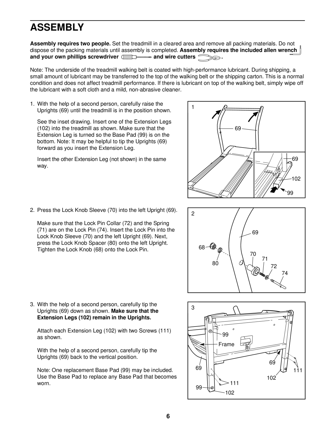
1. With the help of a second person, carefully raise the | 1 |
|
| |
Uprights (69) until the treadmill is in the position shown. |
|
| ||
|
|
| ||
See the inset drawing. Insert one of the Extension Legs |
|
|
| |
(102) into the treadmill as shown. Make sure that the |
|
| 69 | |
Extension Leg is turned so the Base Pad (99) is on the |
|
|
| |
bottom. Note: It may be helpful to tip the Uprights (69) |
|
|
| |
forward as you insert the Extension Leg. |
|
|
|
|
Insert the other Extension Leg (not shown) in the same |
|
| 69 | |
way. |
|
|
|
|
|
|
|
| 102 |
|
|
|
| 99 |
2. Press the Lock Knob Sleeve (70) into the left Upright (69). | 2 |
|
| |
|
|
|
| |
Make sure that the Lock Pin Collar (72) and the Spring |
|
|
| |
(71) are on the Lock Pin (74). Insert the Lock Pin into the |
|
| 69 | |
Lock Knob Sleeve (70) and the left Upright (69). Next, |
|
| ||
|
|
| ||
press the Lock Knob Spacer (80) onto the left Upright. | 68 |
|
| |
Tighten the Lock Knob (68) onto the Lock Pin. |
|
| ||
|
| 70 | ||
|
|
|
| |
|
|
| 80 | 71 |
|
|
| 72 | |
|
|
|
| |
|
|
|
| 74 |
3. With the help of a second person, carefully tip the | 3 |
|
| |
Uprights (69) down as shown. | Make sure that the |
|
| |
|
|
| ||
Extension Legs (102) remain in the Uprights. |
|
|
| |
Attach each Extension Leg (102) with two Screws (111) |
|
| 99 | |
as shown. |
|
|
| |
|
|
|
| |
With the help of a second person, carefully tip the |
|
| Frame | |
|
|
| ||
Uprights (69) back to the vertical position. |
|
| 69 | |
|
| 69 |
| |
Note: One replacement Base Pad (99) may be included. |
| 111 | ||
|
| |||
Use the Base Pad to replace any Base Pad that becomes |
|
| 102 | |
worn. |
| 99 |
| 111 |
|
|
| 102 | |
|
|
|
| |
6