RCR1884 specifications
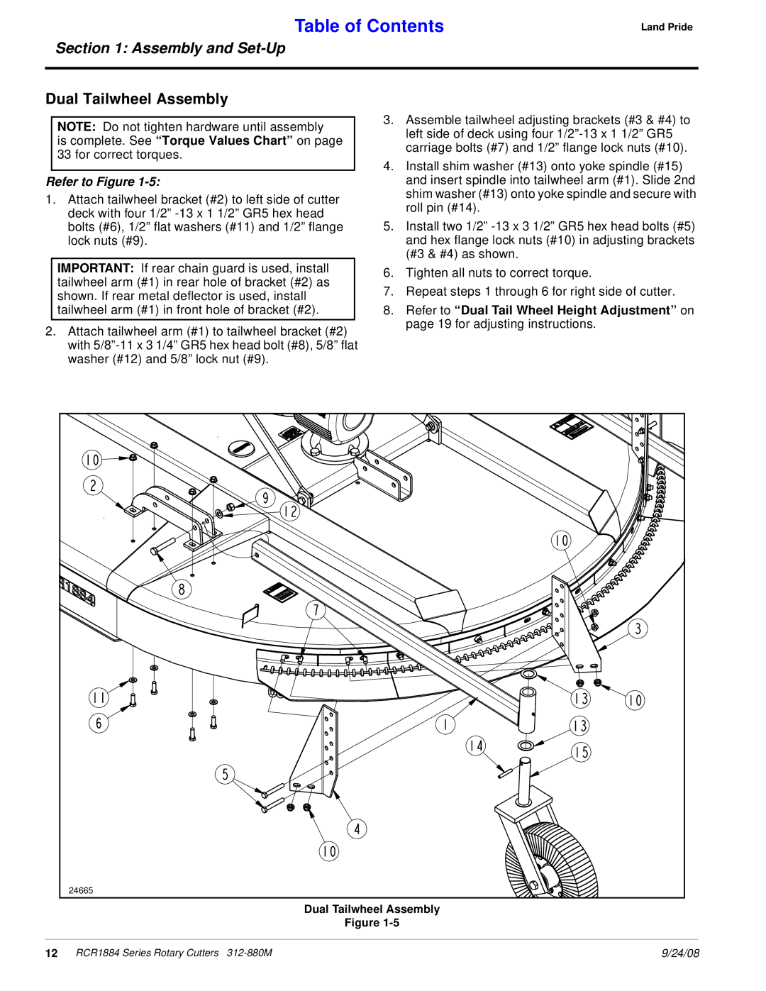
The Land Pride Rotary Cutter RCR1884 is an exceptional piece of equipment designed to meet the needs of landowners, farmers, and contractors looking for reliability and performance in their land management tasks. This rotary cutter is engineered for cutting grass, weeds, and brush, making it an ideal choice for maintaining fields, pastures, and right-of-ways.One of the standout features of the RCR1884 is its cutting width of 84 inches, allowing users to cover a large area efficiently. The heavy-duty construction ensures durability and longevity, with a robust design that can withstand tough operating conditions. The RCR1884 is built with a thick steel frame, ensuring stability and strength while in operation.
Equipped with a powerful gearbox, the RCR1884 delivers consistent power and performance. The gearbox is designed for low maintenance, which reduces downtime and increases productivity. This rotary cutter also features a dual blade system, which provides a smooth and clean cut while minimizing the risk of plugging, making it suitable for different types of terrain.
Safety is a priority in the design of the RCR1884. It is equipped with safety shields and guards that protect the operator from debris and potential hazards during operation. The cutter's slip clutch further enhances safety by protecting the driveline and limiting damage in the event of an unexpected obstruction.
The RCR1884 is designed for easy attachment to tractors, featuring a standard Category 1 hitch that offers versatility and compatibility with a variety of equipment. This makes it a practical choice for users who need to switch tools frequently.
Another notable aspect of the RCR1884 is its ability to handle various cutting conditions. It performs effectively in both light and heavy vegetation, making it suitable for everything from routine lawn care to more intensive brush clearing tasks. The adjustable cutting height allows operators to set the blades at the desired height, ensuring versatility based on specific needs.
In summary, the Land Pride Rotary Cutter RCR1884 is a robust and efficient tool for anyone involved in land management. With its generous cutting width, durable construction, powerful gearbox, and safety features, it is well-equipped to tackle a wide range of cutting tasks. Whether you are maintaining a small property or operating on larger agricultural land, the RCR1884 is designed to deliver reliable performance and exceptional results.

