Tables 3 and 4 show the units' gas pressure requirements
Inlet Gas Supply Pressure
(all models)
Fuel # |
|
| Minimum | Maximum | |
Natural Gas |
| 4.5" WC | 10.5" WC | ||
| (1.12 kPa) | (2.61 kPa) | |||
|
|
| |||
|
|
|
|
|
|
Propane |
|
| 11.0" WC | 13.0" WC | |
|
| (2.73 kPa) | (3.23 kPa) | ||
|
|
| |||
|
|
|
|
|
|
Table 3 |
|
|
|
|
|
|
|
| |||
Manifold Gas Supply Pressure | |||||
|
| (millivolt models) | |||
|
|
|
|
|
|
Fuel # |
|
| Low |
| High |
|
|
|
| ||
Natural | (Lo) 1.6" WC |
| (Hi) 3.5" WC | ||
Gas |
|
| (.40 kPa) |
| (.87 kPa) |
Propane | (Lo) 6.3" WC |
| (Hi) 10.0" WC | ||
| (1.57 kPa) |
| (2.49 kPa) | ||
|
|
| |||
Table 4
Do not use these appliances if any part has been under water. Immediately call a qualified, professional service technician to inspect the appliance and to replace any parts of the control system and any gas controls which have been under water.
Ne pas se servir de cet appareil s'il a été plongé dans l'eau, complètement ou en partie. Appeler un technicien qualifié pour inspecter l'appareil et remplacer toute partie du système de contrôle et toute commande qui ont été plongés dans l'leau.
Test gage connections are provided on the front of the millivolt gas control valve (identified IN for the inlet and OUT for the manifold side).
These appliances must be isolated from the gas supply piping system (by closing their individual manual
These appliances and their individual
These appliances must not be connected to a chimney or flue serving a separate solid fuel burning appliance.
CARBON MONOXIDE POISONING: EARLY SIGNS OF CARBON MONOXIDE POISONING ARESIMILARTOTHEFLUWITHHEADACHES, DIZZINESS AND/OR NAUSEA. IF YOU HAVE THESE SIGNS, OBTAIN FRESH AIR IMMEDI- ATELY. TURN OFF THE GAS SUPPLY TO THE APPLIANCE AND HAVE IT SERVICED BY A QUALIFIED PROFESSIONAL, AS IT MAY NOT BE OPERATING CORRECTLY.
WARNING: FAILURE TO COMPLY WITH THE INSTALLATION AND OPERATING INSTRUC- TIONSPROVIDEDINTHISDOCUMENTWILL RESULT IN AN IMPROPERLY INSTALLED AND OPERATING APPLIANCE, VOIDING ITS WARRANTY. ANY CHANGE TO THIS APPLI- ANCE AND/OR ITS OPERATING CONTROLS ISDANGEROUS. IMPROPERINSTALLATION OR USE OF THIS APPLIANCE CAN CAUSE SERIOUS INJURY OR DEATH FROM FIRE, BURNS, EXPLOSION OR CARBON MONOX- IDE POISONING.
WARNING: CHILDREN AND ADULTS SHOULD BE ALERTED TO THE HAZARDS OF HIGH SURFACE TEMPERATURES. USE CAUTION AROUND THE APPLIANCE TO AVOID BURNS OR CLOTHING IGNITION. YOUNGCHILDRENSHOULDBECAREFULLY SUPERVISEDWHENTHEYAREINTHESAME ROOM AS THE APPLIANCE.
WARNING: DO NOT PLACE CLOTHING OR OTHER FLAMMABLE MATERIALS ON OR NEAR THIS APPLIANCE.
AVERTISSEMENT: SURVEILLER LES ENFANTS. GARDER LES VÊTEMENTS, LES MEUBLES, L'ESSENCE OU AUTRES LIQUIDES À VAPEUR INFLAMMABLES LOIN DE L'APPAREIL.
OPERATION AND CARE OF YOUR APPLIANCE
Appliance operation may be controlled through a remotely located optional wall thermostat or remote control.
In lieu of remote or remote wall thermostat operation, the appliance must be operated directly through the on/off rocker switch located on the upper right side of the rear shield. See Figure 1.
If your millivolt appliance is equipped with an optional wall thermostat kit or remote control kit and the pilot is lit, the appliance main burner may be turned on and off with the wall thermostat or remote control.
NOTE: DIAGRAMS & ILLUSTRATIONS NOT TO SCALE.
Always keep the appliance area clear and free from combustible materials, gasoline and other flammable liquids.
Remember, Millivolt appliances have a continu- ous burning pilot flame. Exercise caution when using products with combustible vapors.
Gas Controls
Burner On/Off Switch
Burner
On /Off
Switch
Top View
Front
Figure 1
Control Compartment Access
The gas controls can be found behind the lower access door. To access, pull the door open (see Figure 2).
Lower Access Door
Pull open lower door to access Valve Contols
Lower Access
Door
Figure 2
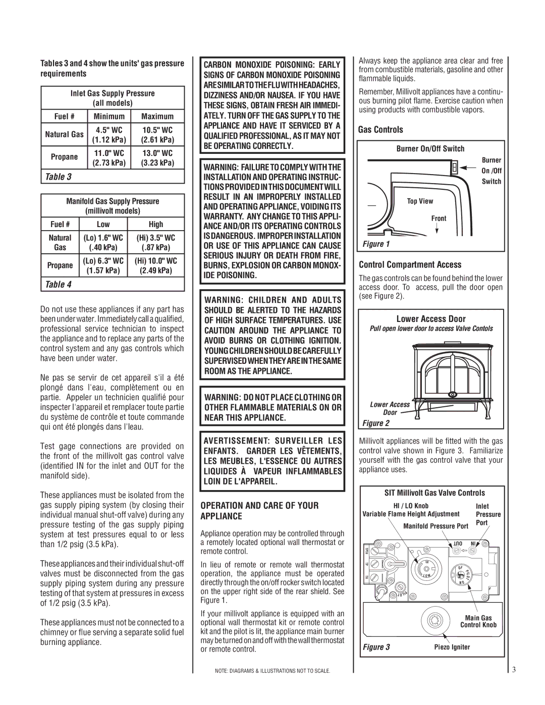
Millivolt appliances will be fitted with the gas control valve shown in Figure 3. Familiarize yourself with the gas control valve that your appliance uses.
SIT Millivolt Gas Valve Controls | ||||
| HI / LO Knob |
|
| Inlet |
Variable Flame Height Adjustment |
| Pressure | ||
| Manifold Pressure Port | Port | ||
|
| |||
|
| OUT |
| IN |
TPTH |
|
|
|
|
TP | IH |
|
|
|
| OF |
|
| |
|
| P |
| |
|
|
|
| |
|
|
| I |
|
TH | L OW |
| L |
|
it | O |
| ||
|
| NO | T |
|
|
|
|
| |
| P |
|
| F |
|
|
|
| |
| LI |
|
|
|
| TO |
|
|
|
|
|
| Main Gas | |
|
| Control Knob | ||
Figure 3 |
| Piezo Igniter |
| |
3