6
Front Glass Enclosure Panel, Removal and Installation.
WARNING: NEVER OPERATE THE APPLIANCE WITHOUT THE GLASS ENCLOSURE PANEL IN PLACE AND SECURE. DO NOT OPERATE APPLIANCE WITH THE FRONT GLASS PANEL CRACKED, BROKEN OR MISSING. REPLACE- MENTPANELSAREAVAILABLETHROUGHYOUR LOCAL LENNOX HEARTH PRODUCTS DEALER AND MUST BE INSTALLED BY A LICENSED OR QUALIFIED SERVICE TECHNICIAN.
These are
During this appliance checkout and adjust- ment period, a potential safety hazard exists
-EXERCISE EXTREME CAUTION to prevent the occurrence of any burn injuries from the exposed flames or hot surfaces. Also note, that while the front glass enclosure panel is removed, the flame will appear to be smaller than normal.
WARNING: HANDLE THE GLASS WITH EXTREME CARE! CERAMIC GLASS IS SUSCEPTIBLE TO DAMAGE (SCRATCHES, FOR EXAMPLE) – HANDLE GLASS DOOR (GLASS ENCLOSURE PANEL) GENTLY WHILE REINSTALLING IT.
WARNING: DO NOT ATTEMPT TO SUBSTITUTE THE MATERIALS USED ON THIS DOOR, OR REPLACE CRACKED OR BROKEN GLASS WITH ANY MATERIALS OTHER THAN THOSE PRO- VIDED BY THE APPLIANCE MANUFACTURER. THE GLASS DOOR OF THIS APPLIANCE MUST ONLY BE REPLACED AS A COMPLETE UNIT AS PROVIDED BY THE MANUFACTURER. DO NOT ATTEMPT TO REPLACE BROKEN, CRACKED OR CHIPPED GLASS SEPARATELY.
1.Remove the trivet, then the cast iron stove top by carefully lifting them up and off and setting them aside (READ CAUTION BELOW).
CAUTION: THE CAST IRON STOVE TOP IS VERY HEAVY AND MAY REQUIRE A MINIMUM OF TWO PEOPLE TO LIFT; ONE PERSON ON EACH SIDE (THE CI1500 SERIES CAST TOP WEIGHS ~20 POUNDS AND THE CI2500 SERIES CAST TOP WEIGHS ~40 POUNDS).
2.Locate and open the 2 latches as shown in Figure 4 (locate below the stove body).
Open both Latches as shown.
Figure 4
3.Reach under the bottom front of the front glass enclosure and pull it forward as shown in figure 5.
Figure 5
4.Lift glass assembly up and out and carefully set aside in a safe place (see figure 6).
Figure 6
To install the front glass enclosure panel, proceed as follows:
1.Retrieve the glass door frame. Visually inspect the gasket on the backside of the panel. The gasket surface must be clean, free of irregularities and seated firmly.
2.With the stove top off, position the glass front enclosure panel into the front open- ing with the gasket facing the relief door (see Figure 6). Let the bottom of the door frame gently slide down, then hook the top flange of the glass frame over the top of the firebox frame.
3.Fasten the two latches located beneath the firebox bottom to the glass frame
4.Reinstall the cast iron stove top (read "Cau- tion," at the bottom of left column).
5.Reinstall Trivet.
NOTE: DIAGRAMS & ILLUSTRATIONS NOT TO SCALE.
Burner Adjustments
The following paragraphs address burner adjustment concerns and procedures.
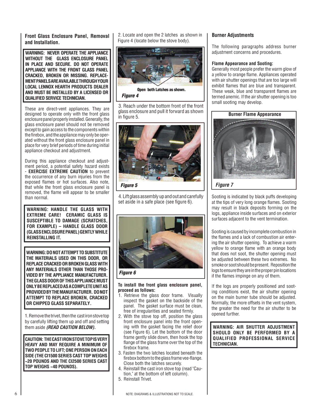
Flame Appearance and Sooting:
Generally most people prefer the warm glow of a yellow to orange flame. Appliances operated with air shutter openings that are too large will exhibit flames that are blue and transparent. These weak, blue and transparent flames are termed anemic. If the air shutter opening is too small sooting may develop.
Burner Flame Appearance
Figure 7
Sooting is indicated by black puffs developing at the tips of very long orange flames. Sooting may result in black deposits forming on the logs, appliance inside surfaces and on exterior surfaces adjacent to the vent termination.
Sooting is caused by incomplete combustion in the flames and a lack of combustion air enter- ing the air shutter opening. To achieve a warm yellow to orange flame with an orange body that does not soot, the shutter opening must be adjusted between these two extremes. No smoke or soot should be present. Reposition the logs to ensure they are in the proper pin locations if the flames impinge on any of them.
If the logs are properly positioned and soot- ing conditions exist, the air shutter opening on the main burner tube should be adjusted. Normally, the more offsets in the vent system, the greater the need for the air shutter to be opened further.
WARNING: AIR SHUTTER ADJUSTMENT SHOULD ONLY BE PERFORMED BY A QUALIFIED PROFESSIONAL SERVICE TECHNICIAN.