L20 DVF-2, L20 BF-2 specifications
The Lennox Hearth L20 DVF-2 and L20 BF-2 are two innovative gas fireplaces that offer modern heating solutions for homes looking to combine functionality, style, and efficiency. Both models are designed with advanced technology to deliver reliable performance and aesthetics that enhance any living space.The L20 DVF-2 is a direct vent fireplace that utilizes a sealed combustion system, allowing it to operate efficiently without drawing air from the room. This feature not only improves energy efficiency but also helps maintain indoor air quality since outside air is used for combustion. One of its standout features is the ability to provide a range of heat output options, allowing homeowners to adjust the warmth to their preference. The fireplace comes with a convenient remote control, enabling effortless operation from anywhere in the room.
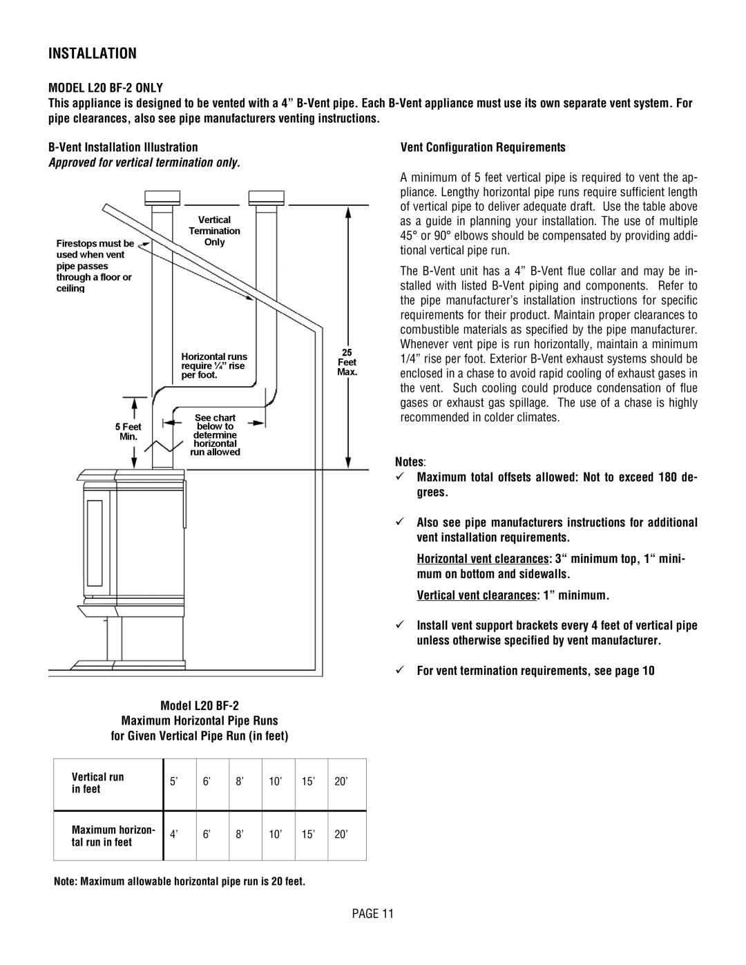
The L20 BF-2, on the other hand, is a conventional vent fireplace, offering a different installation option ideal for various home designs. Similar to the DVF-2, the BF-2 model provides a wide range of heat output, ensuring comfort in chilly conditions. It features a striking design with a large viewing area, allowing for a mesmerizing flame display that serves as a focal point in any room.
Both models are equipped with Lennox's patented Powerflow technology, which optimizes heat distribution throughout the space. This technology not only enhances comfort but also ensures that energy is used efficiently. The fireplaces also feature easy-to-use controls and customizable flame height settings, giving users precise control over their heating experience.
In terms of design, the L20 DVF-2 and L20 BF-2 come in various finishes and styles, allowing them to seamlessly blend with different home aesthetics. Their sleek and contemporary appearance complements modern interiors, while still fitting into more traditional décor in subtle ways.
Overall, the Lennox Hearth L20 DVF-2 and L20 BF-2 provide effective heating solutions paired with advanced technologies and stylish designs. Whether a homeowner desires a direct vent option or a traditional vent fireplace, both models deliver energy-efficient performance, exceptional heat distribution, and a stunning flame display that can enhance the ambiance of any living space. These fireplaces are not just heating appliances; they are an investment into comfort and elegance for years to come.

