TEST ALL CONNECTIONS FOR GAS LEAKS (FACTORY AND FIELD):

WARNING

Never use an open flame to check for leaks.

Turn on gas supply and test for gas leaks using a gas leak test solution (also referred to as bubble leak solution). Note: Using a soapy water solution (50% dish soap, 50% water) is an effective leak test solution but it is not recommended, because the soap residue that is left on the pipes/fittings can result in corrosion over time.

A. Light the appliance (refer to the lighting instructions label in control compartment or homeowner's manual).

B. Brush all joints and connections with the gas leak test solution to check for leaks. If bubbles are formed, or gas odor is detected, turn the gas control knob (off/pilot/on) to the “OFF” position. Either tighten or refasten the leaking connection, then retest as described above.

C.When the gas lines are tested and leak free be sure to rinse off the leak testing solution,

D.Turn on burner then observe the individual tongues of flame on the burner. Make sure all ports are open and producing flame evenly across the burner. If any ports are blocked, or partially blocked, clean out the ports.

CONTROL COMPARTMENT ACCESS /

LOUVER PANEL INSTRUCTIONS (Ref.

Figure 49 )

NOTE: The top louvered panel and the bottom louvered control panel door remove and install the same way as follows:

The gas controls can be found behind the control compartment access door.

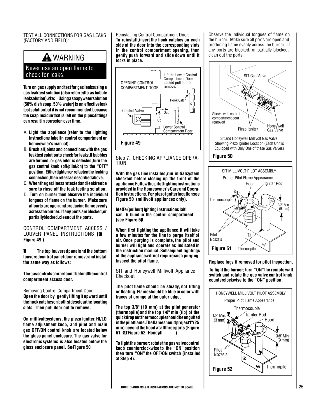
Removing Control Compartment Door: Open the door by gently lifting it upward until the hook catches on both sides clear the locating slots. Then pull door out to remove.

On millivolt systems, the piezo igniter, HI/LO flame adjustment knob, and pilot and main gas OFF/ON control knob are located below the glass panel enclosure. The gas valve for electronic systems is also located below the glass enclosure panel. See Figure 50.

Reinstalling Control Compartment Door:

To reinstall, insert the hook catches on each side of the door into the corresponding slots in the control compartment opening, then gently push forward and slide down until it locks in place.


Lift the Lower Control


Compartment Door

OPENING CONTROL

up and pull out to

COMPARTMENT DOOR

remove.


Hook Catch

Control Valve

Out


Up


Lower Control


Compartment Door

Figure 49

Step 7. Checking Appliance Opera- tion

With the gas line installed, run initial system checkout before closing up the front of the appliance. Follow the pilot lighting instructions provided in the Homeowner's Care and Opera- tion Instructions. For piezo igniter location see Figure 50 (millivolt appliances only).

Note: The (pull-out) Lighting instructions label can be found in the control compartment (see Figure 50).

When first lighting the appliance, it will take a few minutes for the line to purge itself of air. Once purging is complete, the pilot and burner will light and operate as indicated in the instruction manual. Subsequent lightings of the appliance will not require such purging. Inspect the pilot flame.

SIT and Honeywell Millivolt Appliance Checkout

The pilot flame should be steady, not lifting or floating. Flame should be blue in color with traces of orange at the outer edge.

The top 3/8" (10 mm) at the pilot generator (thermopile) and the top 1/8" min (tip) of the quick drop out thermocouple should be engulfed in the pilot flame. The flame should project 1" (25

mm)beyond the hood at all three ports (Figure 51 - SIT, Figure 52 - Honeywell )

To light the burner; rotate the gas valve control knob counterclockwise to the “ON” position then turn “ON” the OFF/ON switch (installed at Step 4).

NOTE: DIAGRAMS & ILLUSTRATIONS ARE NOT TO SCALE.

Observe the individual tongues of flame on the burner. Make sure all ports are open and producing flame evenly across the burner. If any ports are blocked, or partially blocked, clean out the ports.

SIT Gas Valve

Shown with control


compartment door


removed

Honeywell

Piezo Igniter

Gas Valve

Sit and Honeywell Millivolt Gas Valve

Showing Piezo Igniter Location (Each Unit is Equipped with Only One of these Gas Valves)

Figure 50

SIT MILLIVOLT PILOT ASSEMBLY

Proper Pilot Flame Appearance


Hood

Igniter Rod

Thermocouple


3/8" Min.


(9 mm)

Pilot


Nozzels


Figure 51

Thermopile


Replace logs if removed for pilot inspection.

To light the burner; turn “ON” the remote wall switch and rotate the gas valve control knob counterclockwise to the “ON” position.

HONEYWELL MILLIVOLT PILOT ASSEMBLY

Proper Pilot Flame Appearance


Thermocouple

1/8" Min.

Igniter Rod

(3 mm)

Hood

3/8" Min.

(9 mm)

Pilot

Nozzels

Figure 52

Thermopile


25

Page 25
Image 25
Lennox Hearth LMDV-33 Series Control Compartment Access, Louver Panel Instructions Ref, Checking Appliance Opera- tion

LMDV-3530-CNM, LMDV-35 Series, LMDVR-3328-CNE, LMDV-4035-CNE, LMDV-4035-CPM specifications

Lennox Hearth products are renowned for their quality, efficiency, and innovative technologies that optimize the home heating experience. Among the standout offerings in their lineup are the LMDV-3530-CPM, LMDVR-3328-CPM, LMDV-3530-CNE, LMDVT-3328-CPM, and LMDVR-3328-CNM models. Each of these products embodies the brand's commitment to performance and design, making them a popular choice for modern homeowners.

The LMDV-3530-CPM gas fireplace boasts a contemporary aesthetic combined with powerful heating capabilities. It features a clean face design that enhances the viewing experience while maximizing warmth in the room. The unit is equipped with advanced technology that includes multi-speed blowers for efficient air circulation, allowing users to enjoy consistent heat throughout the space. Its variable flame and heat control options ensure that homeowners can customize their ambience and comfort levels according to their preferences.

Similarly, the LMDVR-3328-CPM model is designed for versatility and efficiency. Its modern fireplace insert converts existing masonry fireplaces into high-efficiency heating systems. Featuring a sleek design, this insert incorporates innovative venting technologies that enable it to operate in diverse installation configurations, enhancing both aesthetic appeal and functionality. Homeowners can appreciate the adjustable flame and fan speed settings, which provide tailored heating solutions.

The LMDV-3530-CNE model distinguishes itself through eco-friendly features. It employs advanced combustion technology that reduces emissions without sacrificing heat output. This model stands out as an environmentally responsible option, suitable for conscious consumers who wish to reduce their carbon footprint. Its easy-to-use controls and stylish design make it a favored choice among discerning homeowners.

The LMDVT-3328-CPM continues the trend of performance and versatility. This model combines traditional charm with modern efficiency, featuring a large viewing area that allows for an inviting flame display. The unit’s heat exchanger is designed for maximum heat transfer, ensuring that warmth is efficiently distributed throughout the room.

Lastly, the LMDVR-3328-CNM model is perfect for those seeking an efficient upgrade for their traditional fireplace. With its stunning design and advanced features, including optional remote control and programmable settings, this model takes convenience to new heights.

Overall, Lennox Hearth’s suite of models combines elegance, efficiency, and innovation, ensuring that homeowners can find the perfect heating solution to complement their living spaces. Each product is engineered with state-of-the-art technologies that reflect Lennox’s dedication to quality and customer satisfaction.