12

Vertical Termination Systems (Roof)

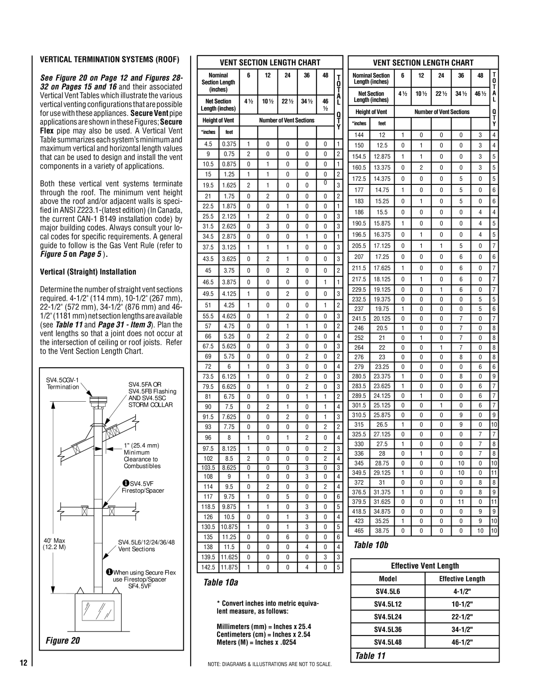
See Figure 20 on Page 12 and Figures 28- 32 on Pages 15 and 16 and their associated Vertical Vent Tables which illustrate the various vertical venting configurations that are possible for use with these appliances. Secure Vent pipe applications are shown in these Figures; Secure Flex pipe may also be used. A Vertical Vent Table summarizes each system’s minimum and maximum vertical and horizontal length values that can be used to design and install the vent components in a variety of applications.

Both these vertical vent systems terminate through the roof. The minimum vent height above the roof and/or adjacent walls is speci- fied in ANSI Z223.1-(latest edition) (In Canada, the current CAN-1 B149 installation code) by major building codes. Always consult your lo- cal codes for specific requirements. A general guide to follow is the Gas Vent Rule (refer to Figure 5 on Page 5 ).

Vertical (Straight) Installation

Determine the number of straight vent sections required. 4-1/2" (114 mm), 10-1/2" (267 mm), 22-1/2" (572 mm), 34-1/2" (876 mm) and 46- 1/2" (1181 mm) net section lengths are available (see Table 11 and Page 31 - Item 3). Plan the vent lengths so that a joint does not occur at the intersection of ceiling or roof joists. Refer to the Vent Section Length Chart.

SV4.5CGV-1

SV4.5FA OR

Termination

SV4.5FB Flashing


AND SV4.5SC


STORM COLLAR


1" (25.4 mm)


Minimum


Clearance to


Combustibles


SV4.5VF


Firestop/Spacer

40' Max

SV4.5L6/12/24/36/48

(12.2

M)

Vent Sections


When using Secure Flex


use Firestop/Spacer


SF4.5VF

Figure 20

VENT SECTION LENGTH CHART

Nominal

6

12

24

36

48

T

Section Length


O

(inches)


T


A

Net Section

4 ½

10 ½

22 ½

34 ½

46

L

Length (inches)


½

Q

Height of Vent


Number of Vent Sections


T


Y

*inches

feet


4.5

0.375

1

0

0

0

0

1


9

0.75

2

0

0

0

0

2

10.5

0.875

0

1

0

0

0

1

15

1.25

1

1

0

0

0

2


19.5

1.625

2

1

0

0

0

3


21

1.75

0

2

0

0

0

2


22.5

1.875

0

0

1

0

0

1

25.5

2.125

1

2

0

0

0

3

31.5

2.625

0

3

0

0

0

3


34.5

2.875

0

0

0

1

0

1


37.5

3.125

1

1

1

0

0

3


43.5

3.625

0

2

1

0

0

3


45

3.75

0

0

2

0

0

2


46.5

3.875

0

0

0

0

1

1


49.5

4.125

1

0

2

0

0

3


51

4.25

1

0

0

0

1

2


55.5

4.625

0

1

2

0

0

3

57

4.75

0

0

1

1

0

2


66

5.25

0

2

2

0

0

4


67.5

5.625

0

0

3

0

0

3


69

5.75

0

0

0

2

0

2

72

6

1

0

3

0

0

4

73.5

6.125

1

0

0

2

0

3


79.5

6.625

0

1

0

2

0

3


81

6.75

0

0

0

1

1

2

90

7.5

0

2

1

0

1

4

91.5

7.625

0

0

2

0

1

3


93

7.75

0

0

0

0

2

2


96

8

1

0

1

2

0

4


97.5

8.125

1

0

0

0

2

3


102

8.5

2

0

0

0

2

4


103.5

8.625

0

0

0

3

0

3

108

9

1

0

0

3

0

4

114

9.5

0

2

0

0

2

4

117

9.75

1

0

5

0

0

6


118.5

9.875

1

1

0

3

0

5


126

10.5

0

0

1

3

0

4


130.5

10.875

1

0

1

3

0

5

135

11.25

0

0

6

0

0

6

138

11.5

0

0

0

4

0

4


139.5

11.625

0

0

0

0

3

3


142.5

11.875

1

0

0

4

0

5


Table 10a

*Convert inches into metric equiva- lent measure, as follows:

Millimeters (mm) = Inches x 25.4

Centimeters (cm) = Inches x 2.54

Meters (M) = Inches x .0254

NOTE: DIAGRAMS & ILLUSTRATIONS ARE NOT TO SCALE.

VENT SECTION LENGTH CHART

Nominal Section

6

12

24

36

48

T

Length (inches)


O


T


Net Section

4 ½

10 ½

22 ½

34 ½

46 ½

A

Length (inches)


L


Q

Height of Vent


Number of Vent Sections


T

*inches

feet


Y


144

12

1

0

0

0

3

4

150

12.5

0

1

0

0

3

4


154.5

12.875

1

1

0

0

3

5


160.5

13.375

0

2

0

0

3

5


172.5

14.375

0

0

0

5

0

5


177

14.75

1

0

0

5

0

6


183

15.25

0

1

0

5

0

6


186

15.5

0

0

0

0

4

4


190.5

15.875

1

0

0

0

4

5


196.5

16.375

0

1

0

0

4

5


205.5

17.125

0

1

1

5

0

7


207

17.25

0

0

0

6

0

6


211.5

17.625

1

0

0

6

0

7


217.5

18.125

0

1

0

6

0

7


229.5

19.125

0

0

1

6

0

7

232.5

19.375

0

0

0

0

5

5

237

19.75

1

0

0

0

5

6

241.5

20.125

0

0

0

7

0

7

246

20.5

1

0

0

7

0

8

252

21

0

1

0

7

0

8

264

22

0

0

1

7

0

8

276

23

0

0

0

8

0

8

279

23.25

0

0

0

0

6

6

280.5

23.375

1

0

0

8

0

9

283.5

23.625

1

0

0

0

6

7

289.5

24.125

0

1

0

0

6

7

301.5

25.125

0

0

1

0

6

7

310.5

25.875

0

0

0

9

0

9

315

26.5

1

0

0

9

0

10

325.5

27.125

0

0

0

0

7

7

330

27.5

1

0

0

0

7

8

336

28

0

1

0

0

7

8

345

28.75

0

0

0

10

0

10

349.5

29.125

1

0

0

10

0

11

372

31

0

0

0

0

8

8

376.5

31.375

1

0

0

0

8

9

379.5

31.625

0

0

0

11

0

11

418.5

34.875

0

0

0

0

9

9

423

35.25

1

0

0

0

9

10

465

38.75

0

0

0

0

10

10


Table 10b

Effective Vent Length

Model

Effective Length


SV4.5L6

4-1/2"


SV4.5L12

10-1/2"


SV4.5L24

22-1/2"


SV4.5L36

34-1/2"


SV4.5L48

46-1/2"


Table 11

Page 12
Image 12
Lennox Hearth LMDV-3530-CNE Vertical Termination Systems Roof, Vertical Straight Installation, Vent Section Length Chart

LMDV-3530-CNM, LMDV-35 Series, LMDVR-3328-CNE, LMDV-4035-CNE, LMDV-4035-CPM specifications

Lennox Hearth products are renowned for their quality, efficiency, and innovative technologies that optimize the home heating experience. Among the standout offerings in their lineup are the LMDV-3530-CPM, LMDVR-3328-CPM, LMDV-3530-CNE, LMDVT-3328-CPM, and LMDVR-3328-CNM models. Each of these products embodies the brand's commitment to performance and design, making them a popular choice for modern homeowners.

The LMDV-3530-CPM gas fireplace boasts a contemporary aesthetic combined with powerful heating capabilities. It features a clean face design that enhances the viewing experience while maximizing warmth in the room. The unit is equipped with advanced technology that includes multi-speed blowers for efficient air circulation, allowing users to enjoy consistent heat throughout the space. Its variable flame and heat control options ensure that homeowners can customize their ambience and comfort levels according to their preferences.

Similarly, the LMDVR-3328-CPM model is designed for versatility and efficiency. Its modern fireplace insert converts existing masonry fireplaces into high-efficiency heating systems. Featuring a sleek design, this insert incorporates innovative venting technologies that enable it to operate in diverse installation configurations, enhancing both aesthetic appeal and functionality. Homeowners can appreciate the adjustable flame and fan speed settings, which provide tailored heating solutions.

The LMDV-3530-CNE model distinguishes itself through eco-friendly features. It employs advanced combustion technology that reduces emissions without sacrificing heat output. This model stands out as an environmentally responsible option, suitable for conscious consumers who wish to reduce their carbon footprint. Its easy-to-use controls and stylish design make it a favored choice among discerning homeowners.

The LMDVT-3328-CPM continues the trend of performance and versatility. This model combines traditional charm with modern efficiency, featuring a large viewing area that allows for an inviting flame display. The unit’s heat exchanger is designed for maximum heat transfer, ensuring that warmth is efficiently distributed throughout the room.

Lastly, the LMDVR-3328-CNM model is perfect for those seeking an efficient upgrade for their traditional fireplace. With its stunning design and advanced features, including optional remote control and programmable settings, this model takes convenience to new heights.

Overall, Lennox Hearth’s suite of models combines elegance, efficiency, and innovation, ensuring that homeowners can find the perfect heating solution to complement their living spaces. Each product is engineered with state-of-the-art technologies that reflect Lennox’s dedication to quality and customer satisfaction.