LENNOX HEARTH PRODUCTS • MONTEBELLO®
ORDERING Replacement parts
A complete parts list is found at the end of this manual. Use only parts supplied from the manufacturer.
With proper care and maintenance, your appli- ance will provide many years of enjoyment. If you should experience any problem, first refer to the troubleshooting guide in this manual. If the problem persists, contact your Lennox Hearth Products dealer or distributor.
Order parts through your Lennox Hearth Prod- ucts distributor or dealer. Parts will be shipped at prevailing prices at time of order.
If you encounter any problems or have any questions concerning the installation or ap- plication of this system, please contact your dealer or distributor.
PRODUCT REFERENCE
INFORMATION
We recommend that you record the important reference information about your fireplace in the space provided below.
Please call Lennox Hearth Products for the phone number of your nearest LHP dealer, who will answer your questions or address your concerns.
LENNOX hEARTH pRODUCTS 1508 Elm Hill Pike, Suite 108 Nashville, TN 37210
Visit us at www.Lennox.com
Product Reference Information
Cat. | Model | Ship. | Ship. | |
No. | Wt. | Volume | ||
| ||||
|
|
|
| |
H7937 | 382 lb. | 51.25 cu. ft. | ||
|
|
|
| |
H7938 | 382 lb. | 51.25 cu. ft. | ||
|
|
|
|
When ordering parts, provide the following information:
1.Appliance model number.
2.Appliance serial number.
3.Part number.
4.Part description.
5.Quantity required.
6.Appliance installation date.
PRODUCT REFERENCE INFORMATION
Model Number_________________________________________________________
Serial Number_________________________________________________________
Date Installed _ ________________________________________________________
Gas Type Used_________________________________________________________
Dealer Name __________________________________________________________
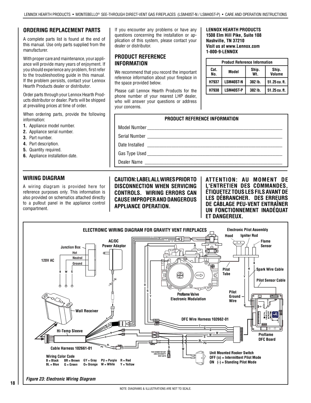
Wiring Diagram
A wiring diagram is provided here for reference purposes only. This information is also provided on schematics attached directly to a pullout panel in the appliance control compartment.
CAUTION:LABELALLWIRESPRIORTO DISCONNECTION WHEN SERVICING CONTROLS. WIRING ERRORS CAN CAUSE IMPROPER AND DANGEROUS APPLIANCE OPERATION.
ATTENTION: AU MOMENT DE L'ENTRETIEN DES COMMANDES, ÉTIQUETEZ TOUS LES FILS AVANT DE LES DÉBRANCHER. DES ERREURS DE CÁBLAGE
18
|
| ELECTRONIC WIRING DIAGRAM FOR GRAVITY VENT FIREPLACES | Electronic Pilot Assembly | ||||||
|
|
|
| B | BR |
|
| Hood | Igniter Rod |
|
| AC/DC |
|
| Y |
|
| Flame | |
|
|
|
|
| O |
| |||
|
|
|
|
|
|
|
|
| |
| Junction Box | Power Adaptor |
|
|
|
|
|
| Sensor |
|
|
|
|
|
|
|
|
| |
| Hot |
|
|
|
|
|
|
|
|
120V AC | Neutral |
|
|
|
|
|
|
|
|
Ground |
|
|
|
|
|
|
| B | |
|
|
|
|
|
|
|
| ||
| B W G |
|
|
|
|
|
| Pilot | R Spark Wire Cable |
|
|
|
|
|
|
| Tube |
| |
|
|
|
|
|
|
|
| Y | |
|
|
|
|
|
|
|
|
| |
|
|
|
|
|
|
|
|
| Pilot Sensor Cable |
|
|
| O |
|
|
|
|
|
|
|
|
| G |
|
|
| Proflame Valve | Pilot |
|
|
|
|
|
|
|
|
| ||
|
|
| Y |
|
|
| Ground |
| |
|
|
|
|
|
| Electronic Modulation |
| ||
|
|
|
|
|
|
| Wire |
| |
|
|
|
|
|
|
|
|
| |
| Wall Receiver |
|
|
|
|
|
|
| |
|
| R GY |
|
|
|
| DFC Wire Harness |
| |
|
| B |
| Y |
|
|
|
|
|
| BR |
| G |
|
|
| |
Y | O |
|
| O |
|
| ||
|
|
|
|
|
|
| ||
| W |
|
|
| W | W | Proflame | |
|
|
|
|
| ||||
|
| G |
|
| G |
| ||
|
|
|
|
|
| DFC Board | ||
|
|
|
| BL | PU |
|
| |
|
| BL |
|
|
|
| ||
Cable Harness | PU | G |
|
|
|
|
| |
| W |
|
|
|
| |||
|
|
|
|
|
|
|
|
|
|
| USED ON GRAVITY | Unit Mounted Rocker Switch | |
Wiring Color Code |
|
| THIS CONNECTOR NOT | OFF (o) = Intermittent Pilot Mode | ||
|
| VENT UNITS | ||||
B = Black | BR = Brown | GY = Gray | PU = Purple | R = Red | ON | |
BL = Blue | G = Green | O= Orange | W = White | Y = Yellow | ||
| ||||||
Figure 23: Electronic Wiring Diagram
NOTE: DIAGRAMS & ILLUSTRATIONS ARE NOT TO SCALE.