Cooling Mode (Dehumidification OFF)
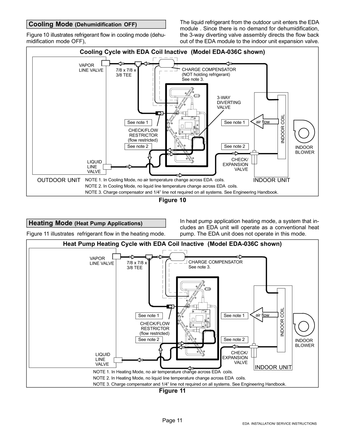
Figure 10 illustrates refrigerant flow in cooling mode (dehu- midification mode OFF),
The liquid refrigerant from the outdoor unit enters the EDA module . Since there is no demand for dehumidification, the 3−way diverting valve assembly directs the flow back out of the EDA module to the indoor unit expansion valve.
Cooling Cycle with EDA Coil Inactive (Model EDA−036C shown)
VAPOR
LINE VALVE 7/8 x 7/8 x 3/8 TEE
See note 1
CHECK/FLOW RESTRICTOR (flow restricted)
See note 2
LIQUID
LINE
VALVE
CHARGE COMPENSATOR (NOT holding refrigerant) See note 3.
3−WAY
DIVERTING VALVE
See note 1
See note 2
CHECK/
EXPANSION
VALVE
air flow | COIL |
| INDOOR |
INDOOR BLOWER
OUTDOOR UNIT NOTE 1. In Cooling Mode, no air temperature change across EDA coils. NOTE 2. In Cooling Mode, no liquid line temperature change across EDA coils.
INDOOR UNIT
NOTE 3. Charge compensator and 1/4" line not required on all systems. See Engineering Handbook.
Figure 10
Heating Mode (Heat Pump Applications)
Figure 11 illustrates refrigerant flow in the heating mode.
In heat pump application heating mode, a system that in- cludes an EDA unit will operate as a conventional heat pump. The EDA unit does not operate in this mode.
Heat Pump Heating Cycle with EDA Coil Inactive (Model EDA−036C shown)
VAPOR
LINE VALVE 7/8 x 7/8 x 3/8 TEE
See note 1
CHECK/FLOW RESTRICTOR (flow restricted)
See note 2
LIQUID
LINE
VALVE
CHARGE COMPENSATOR See note 3.
See note 1
See note 2
CHECK/
EXPANSION
VALVE
|
| COIL |
air flow | ||
|
| INDOOR |
|
|
|
INDOOR UNIT
INDOOR BLOWER
NOTE 1. In Heating Mode, no air temperature change across EDA coils. NOTE 2. In Heating Mode, no liquid line temperature change across EDA coils.
NOTE 3. Charge compensator and 1/4" line not required on all systems. See Engineering Handbook.
Figure 11
Page 11
EDA INSTALLATION/ SERVICE INSTRUCTIONS