Component Functions
Charge Compensator
(shown in figure 5) serves to maintain the proper amount of refrigerant circulating in larger systems. [Some systems do not require a charge compensator, but do require a simi- lar kit to connect into the system (see Engineering Hand- book)]
The charge compensator stores excess refrigerant when the EDA coil is active and returns it to the system during normal cooling or heating operations. When the EDA coil is active, less charge is required to obtain the proper amount of subcooling because of the additional coil surface and the cooler air which passes over the EDA coil.
Check/Flow Restrictorcheck function of the check/flow restrictor (shown in figure 2) prevents refriger- ant from flowing into the inactive components during times when the EDA coil is inactive. The flow restrictor controls the rate of return of charge to the system from the charge compensator and the EDA coil when the system changes from "EDA coil active" to "EDA coil inactive."
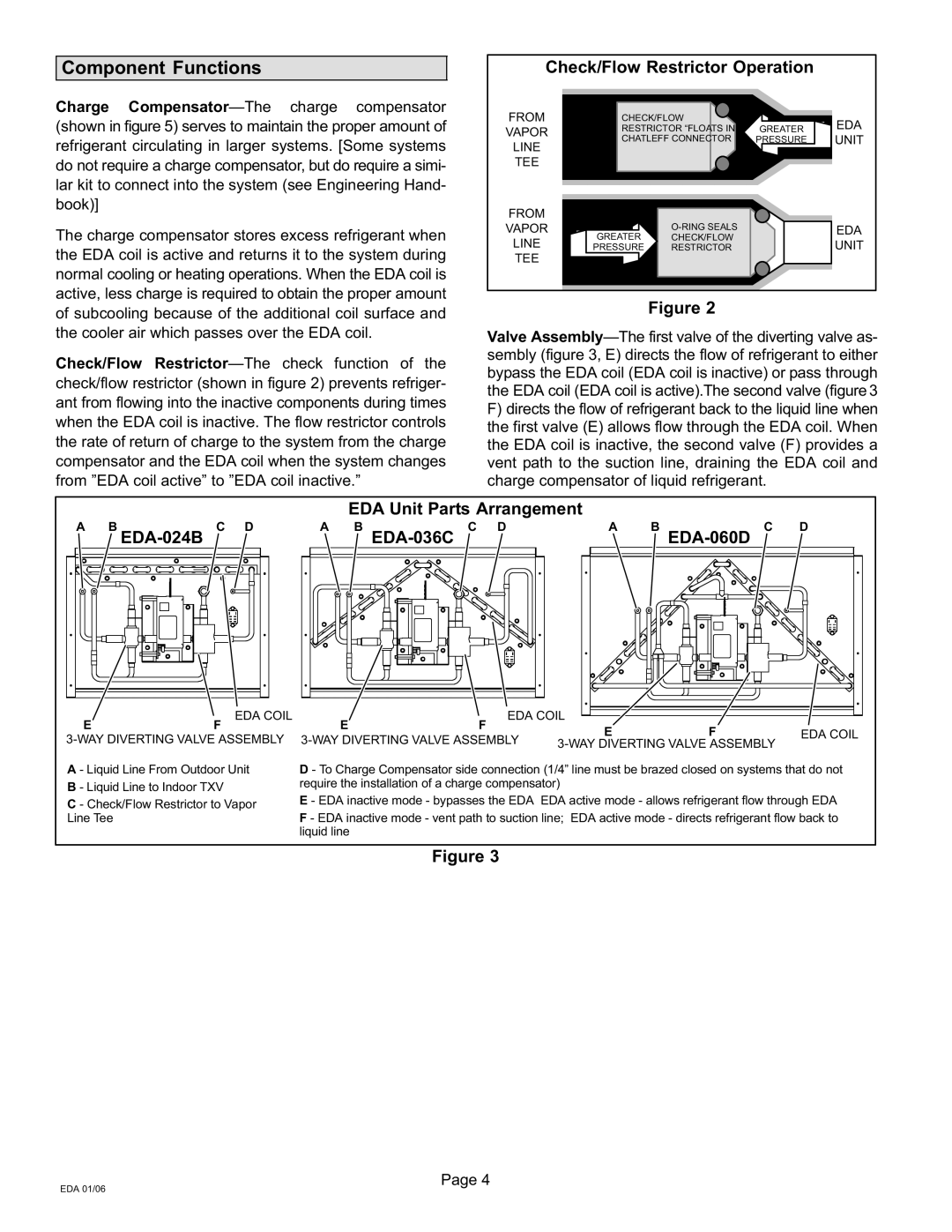
Check/Flow Restrictor Operation
FROM | CHECK/FLOW |
| EDA | |
VAPOR | RESTRICTOR TS IN | GREATER | ||
| ||||
CHATLEFF CONNECTOR | PRESSURE | UNIT | ||
LINE | ||||
|
|
| ||
TEE |
|
|
|
FROM |
|
|
| |
VAPOR |
| O−RING SEALS | EDA | |
GREATER | CHECK/FLOW | |||
LINE | UNIT | |||
PRESSURE | RESTRICTOR | |||
TEE |
|
|
|
Figure 2
Valve Assembly
sembly (figure 3, E) directs the flow of refrigerant to either bypass the EDA coil (EDA coil is inactive) or pass through the EDA coil (EDA coil is active).The second valve (figure 3
F)directs the flow of refrigerant back to the liquid line when the first valve (E) allows flow through the EDA coil. When the EDA coil is inactive, the second valve (F) provides a vent path to the suction line, draining the EDA coil and charge compensator of liquid refrigerant.
EDA Unit Parts Arrangement
A B | C D | A B | C D | A | B | C D |
EDA−024B |
| EDA−036C |
|
|
| EDA−060D |
| EDA COIL |
|
| EDA COIL |
|
| ||
E | F | E | F |
| E | F | EDA COIL | |
3−WAY DIVERTING VALVE ASSEMBLY | 3−WAY DIVERTING VALVE ASSEMBLY | |||||||
3−WAY DIVERTING VALVE ASSEMBLY |
| |||||||
|
|
|
|
|
| |||
A − Liquid Line From Outdoor Unit B − Liquid Line to Indoor TXV
C − Check/Flow Restrictor to Vapor Line Tee
D − To Charge Compensator side connection (1/4" line must be brazed closed on systems that do not require the installation of a charge compensator)
E − EDA inactive mode − bypasses the EDA EDA active mode − allows refrigerant flow through EDA
F − EDA inactive mode − vent path to suction line; EDA active mode − directs refrigerant flow back to liquid line
Figure 3
Page 4
EDA 01/06