Leak Testing, Evacuating, Charging
![]() IMPORTANT
IMPORTANT
Prior to starting the outdoor unit for charging, be
IMPORTANT sure the
The 3−way diverting valve actuator shaft setscrew | 3. Very little charge is required for the additional volume | |
(see figure 7) is factory set and is not to be adjusted. | ||
of the EDA unit. When in normal cooling, the compo- | ||
| ||
| nents will all be occupied by vapor that has very little | |
3−way Diverting Valve Operation | weight. At most (depending on the model) an addition- | |
NOTE − During system operation, the | al 1/4 pound of refrigerant may be required. | |
4. When shifting from dehumidify mode to cooling, or | ||
tion. | vice versa, wait at least 10 minutes for the system to | |
The 3−way diverting valve is actually two valves connected | reach stable operating pressure before checking tem- | |
by a common shaft, designed to open one valve while clos- | peratures and pressures, or adjusting refrigerant | |
ing the other, and vice versa. For evacuating (with power | charge. | |
off), the diverting valve can be REPOSITIONED using its | NOTE − Prior to starting the outdoor unit for charging, | |
actuator lever, a long setscrew that has been | ||
set the thermostat to call for cooling (dehumidification | ||
a precise point on the common shaft. Do not loosen (un- | ||
OFF). It will take about 90 seconds for the 3−way di- | ||
screw) the setscrew. Should the setscrew become | ||
verting valve to energize and shift to the cooling posi- | ||
loose, carefully follow the note in figure 6 to position | ||
tion. To ensure that the | ||
and tighten it. | ||
gized and in the | ||
| ||
| the position of the | |
Re−aligning Setscrew | setscrew in figure 7; if properly shifted, the setscrew | |
will be in the forward position. | ||
| ||
NOTE − Actuator shaft setscrew is factory set and must not be ad- |
| |
justed. If the set screw should become loose, use a pliers to grip the | Setting 3−Way Diverting Valve to | |
shaft where shown (1) and rotate the shaft (in direction of the black | ||
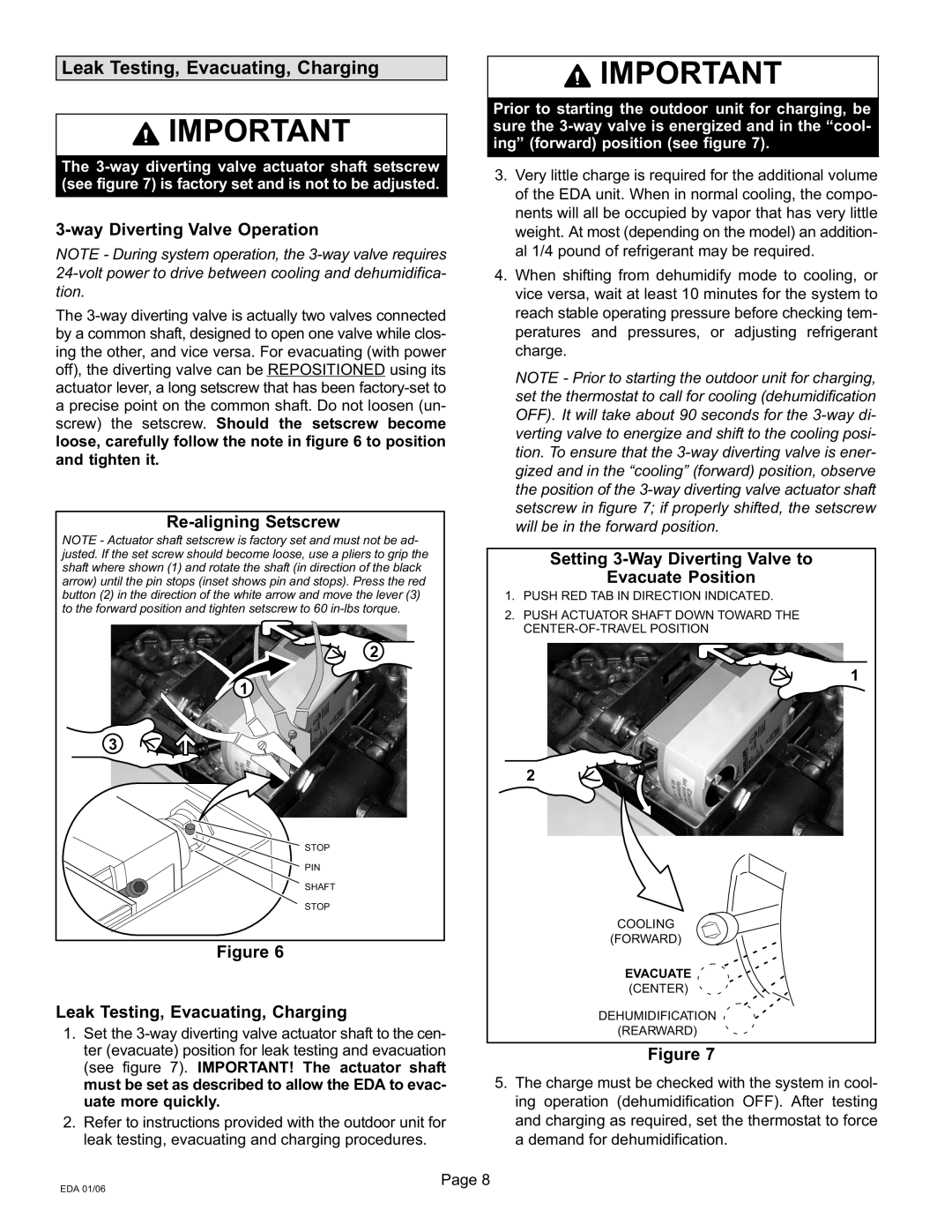
Evacuate Position | ||
arrow) until the pin stops (inset shows pin and stops). Press the red | ||
button (2) in the direction of the white arrow and move the lever (3) | 1. PUSH RED TAB IN DIRECTION INDICATED. | |
to the forward position and tighten setscrew to 60 | 2. PUSH ACTUATOR SHAFT DOWN TOWARD THE | |
| ||
| CENTER−OF−TRAVEL POSITION | |
2 |
| |
1 | 1 | |
|
3
2
STOP |
|
PIN |
|
SHAFT |
|
STOP |
|
| COOLING |
Figure 6 | (FORWARD) |
| |
| EVACUATE |
| (CENTER) |
Leak Testing, Evacuating, Charging | DEHUMIDIFICATION |
1. Set the 3−way diverting valve actuator shaft to the cen- | (REARWARD) |
ter (evacuate) position for leak testing and evacuation | Figure 7 |
(see figure 7). IMPORTANT! The actuator shaft |
|
must be set as described to allow the EDA to evac- | 5. The charge must be checked with the system in cool- |
uate more quickly. | ing operation (dehumidification OFF). After testing |
2. Refer to instructions provided with the outdoor unit for | and charging as required, set the thermostat to force |
leak testing, evacuating and charging procedures. | a demand for dehumidification. |
Page 8 |
|
EDA 01/06 |
|