Air Resistance
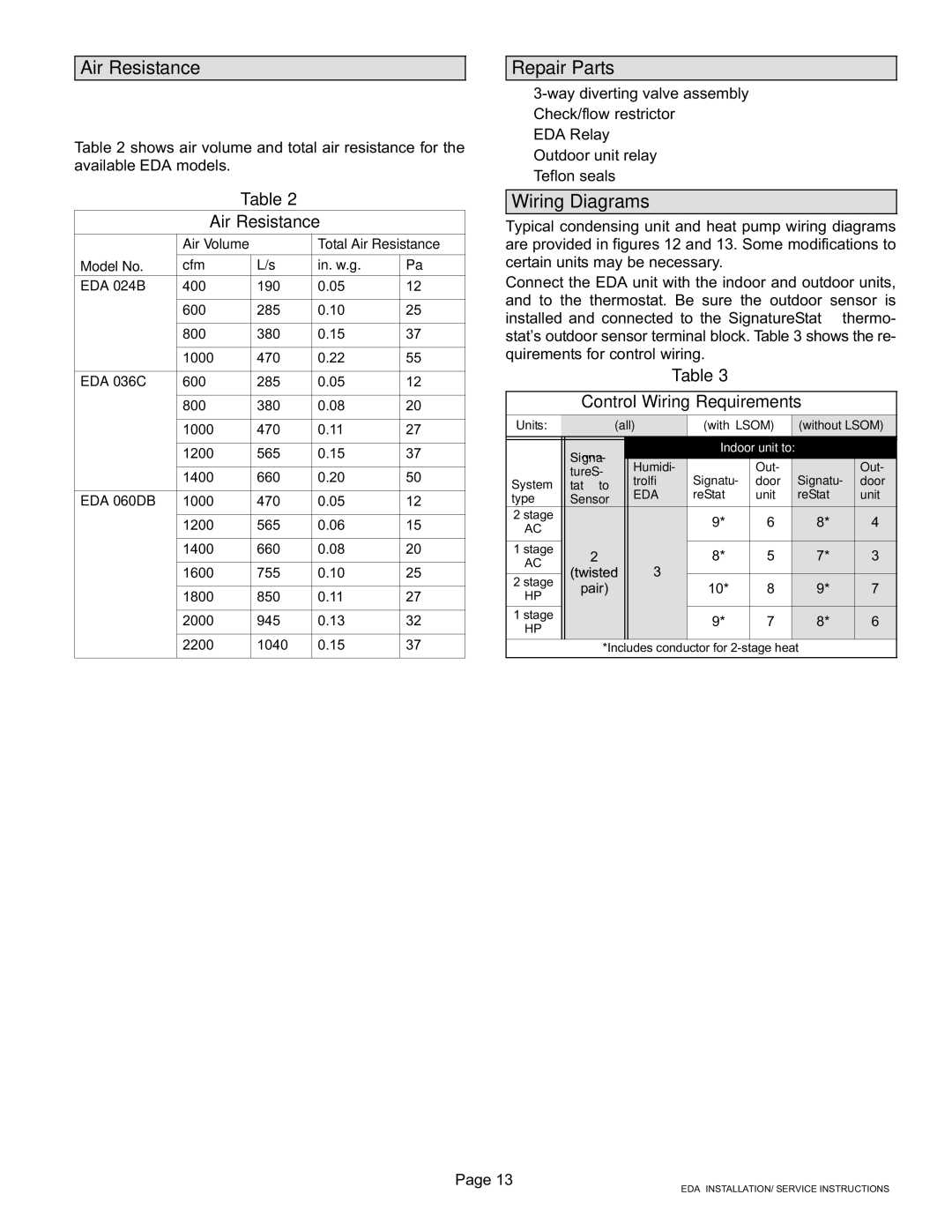
Table 2 shows air volume and total air resistance for the available EDA models.
Table 2
Air Resistance
| Air Volume |
| Total Air Resistance | ||
|
|
|
|
| |
Model No. | cfm |
| L/s | in. w.g. | Pa |
EDA−024B | 400 |
| 190 | 0.05 | 12 |
|
|
|
|
|
|
| 600 |
| 285 | 0.10 | 25 |
|
|
|
|
|
|
| 800 |
| 380 | 0.15 | 37 |
|
|
|
|
|
|
| 1000 |
| 470 | 0.22 | 55 |
|
|
|
|
|
|
EDA−036C | 600 |
| 285 | 0.05 | 12 |
|
|
|
|
|
|
| 800 |
| 380 | 0.08 | 20 |
|
|
|
|
|
|
| 1000 |
| 470 | 0.11 | 27 |
|
|
|
|
|
|
| 1200 |
| 565 | 0.15 | 37 |
|
|
|
|
|
|
| 1400 |
| 660 | 0.20 | 50 |
|
|
|
|
|
|
EDA−060DB | 1000 |
| 470 | 0.05 | 12 |
|
|
|
|
|
|
| 1200 |
| 565 | 0.06 | 15 |
|
|
|
|
|
|
| 1400 |
| 660 | 0.08 | 20 |
|
|
|
|
|
|
| 1600 |
| 755 | 0.10 | 25 |
|
|
|
|
|
|
| 1800 |
| 850 | 0.11 | 27 |
|
|
|
|
|
|
| 2000 |
| 945 | 0.13 | 32 |
|
|
|
|
|
|
| 2200 |
| 1040 | 0.15 | 37 |
|
|
|
|
|
|
Repair Parts
S3−way diverting valve assembly
SCheck/flow restrictor
SEDA Relay
SOutdoor unit relay
STeflon seals
Wiring Diagrams
Typical condensing unit and heat pump wiring diagrams are provided in figures 12 and 13. Some modifications to certain units may be necessary.
Connect the EDA unit with the indoor and outdoor units, and to the thermostat. Be sure the outdoor sensor is installed and connected to the SignatureStatt thermo- stat’s outdoor sensor terminal block. Table 3 shows the re- quirements for control wiring.
Table 3
Control Wiring Requirements
Units: | (all) | (with LSOM) | (without LSOM) |
| |||
| Signa- |
| Indoor unit to: |
|
| ||
|
|
|
|
|
|
| |
| tureS- | Humidi- |
| Out- |
| Out- |
|
| trol® | Signatu- | door | Signatu- | door |
| |
System | tatt to |
| |||||
EDA | reStatt | unit | reStatt | unit |
| ||
type | Sensor |
| |||||
|
|
|
|
|
| ||
2 stage |
|
| 9* | 6 | 8* | 4 |
|
AC |
|
|
| ||||
|
|
|
|
|
|
| |
|
|
|
|
|
|
|
|
1 stage | 2 |
| 8* | 5 | 7* | 3 |
|
AC |
|
| |||||
(twisted | 3 |
|
|
|
|
| |
2 stage |
|
|
|
|
| ||
pair) |
| 10* | 8 | 9* | 7 |
| |
HP |
|
| |||||
|
|
|
|
|
|
| |
1 stage |
|
| 9* | 7 | 8* | 6 |
|
HP |
|
|
| ||||
|
|
|
|
|
|
| |
| *Includes conductor for 2−stage heat |
|
| ||||
|
|
|
|
|
|
|
|
Page 13
EDA INSTALLATION/ SERVICE INSTRUCTIONS