When installing: Plug the gray cable into the jack marked MAIN or M, and the black cable into the jack marked AUX or A on the card.
Note: In models with a wireless LAN card that has three antenna connectors, plug the gray cable (MAIN) into the jack marked TR1, the white cable (third) into the jack marked RO or TR3, and the black cable (AUX) into the jack marked TR2 on the card.
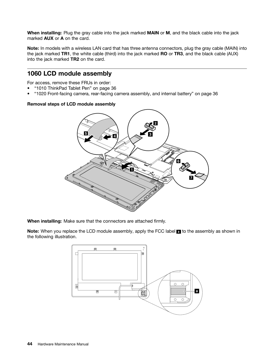
1060 LCD module assembly
For access, remove these FRUs in order:
•“1010 ThinkPad Tablet Pen” on page 36
•“1020
Removal steps of LCD module assembly
5
![]() 4
4
![]() 2
2
3
6 |
1
7 ![]()
![]()
When installing: Make sure that the connectors are attached firmly.
Note: When you replace the LCD module assembly, apply the FCC label ![]()
![]()
![]() to the assembly as shown in the following illustration.
to the assembly as shown in the following illustration.
a