6435, 6436, 6437, 6438 specifications
Lenovo has continuously pushed the boundaries of technology with its innovative offerings in the laptop segment. Among its diverse portfolio, the Lenovo 6438, 6437, 6435, and 6436 models stand out due to their advanced features and robust performance, catering to both professional and everyday users.The Lenovo 6438 is notable for its striking design and powerful specifications. It typically includes Intel's latest processors, ensuring smooth multitasking and enhanced performance. With an ample amount of RAM, users can seamlessly switch between applications. It often comes equipped with a high-resolution display, providing vibrant colors and sharp visuals, ideal for both work and entertainment.
Moving on to the Lenovo 6437, this model emphasizes portability without sacrificing functionality. Weighing less than its counterparts, it is a favorite among students and professionals on the go. The model features an impressive battery life, providing extended usage hours, making it perfect for long flights or extended meetings. The touchscreen capability adds an extra layer of interactivity, allowing for intuitive use.
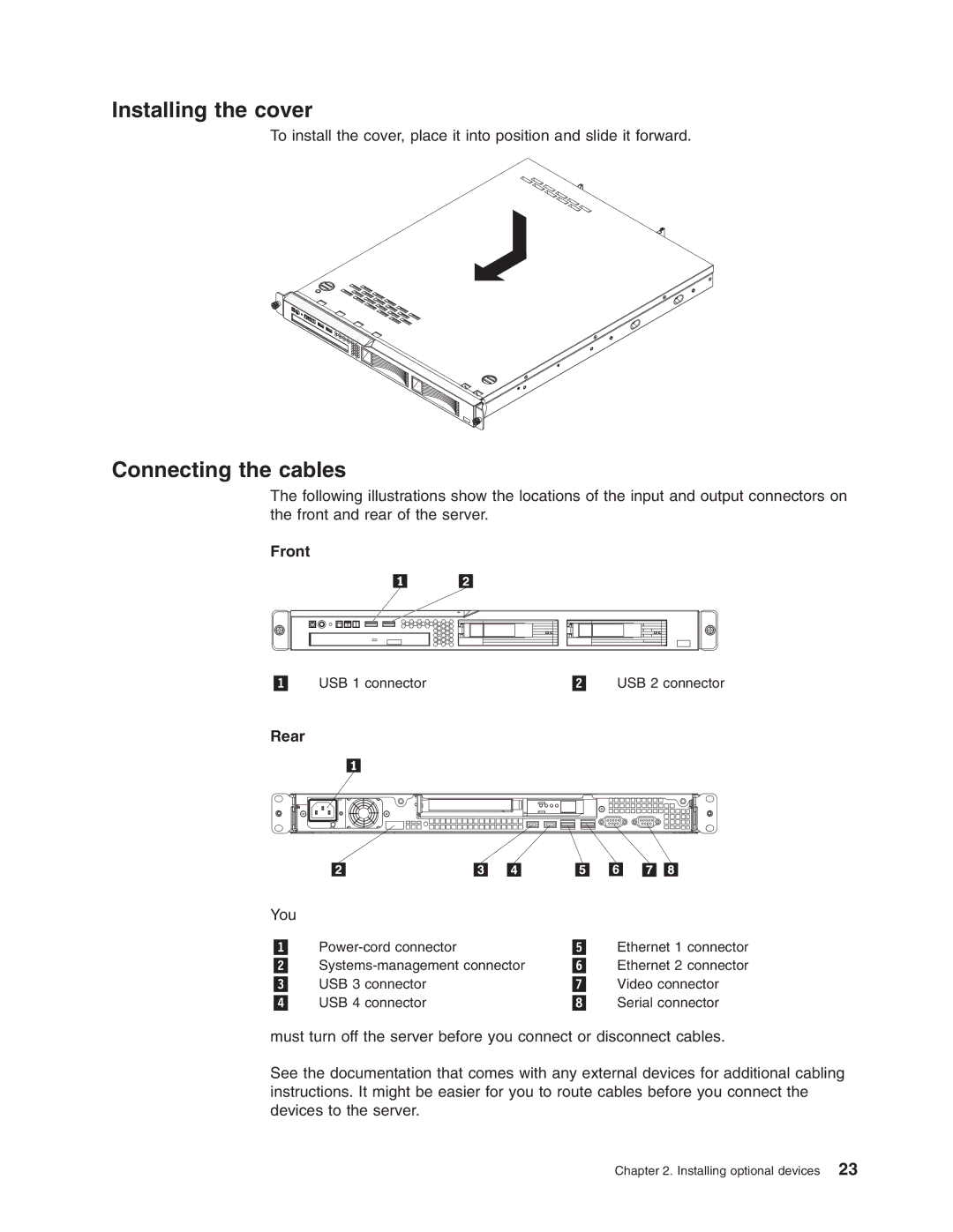
The Lenovo 6435 distinguishes itself with its focus on security and connectivity. It often integrates biometric security features, such as a fingerprint reader, ensuring that user data remains safe. Furthermore, it typically includes multiple USB ports along with HDMI and Ethernet connections, catering to a range of peripheral devices. As for connectivity, it usually supports the latest Wi-Fi standards for faster and more reliable internet access.
Finally, the Lenovo 6436 is tailored for gamers and heavy multimedia users. It generally boasts a dedicated graphics card, delivering exceptional graphic performance for gaming and design work. The cooling system in this model is often engineered to ensure optimal performance during intense usage. Additionally, the sound quality is enhanced, with Dolby Audio technology providing an immersive audio experience.
In summary, the Lenovo 6438, 6437, 6435, and 6436 models exemplify the brand's commitment to innovation. With their unique features tailored for various user needs, these models present an excellent choice for anyone looking for performance, portability, security, or gaming capabilities. Whether for business, creativity, or leisure, Lenovo consistently provides quality and reliability in its laptop offerings.

