Lenovo IdeaPad Tablet
 A1-07 Hardware Maintenance Manual
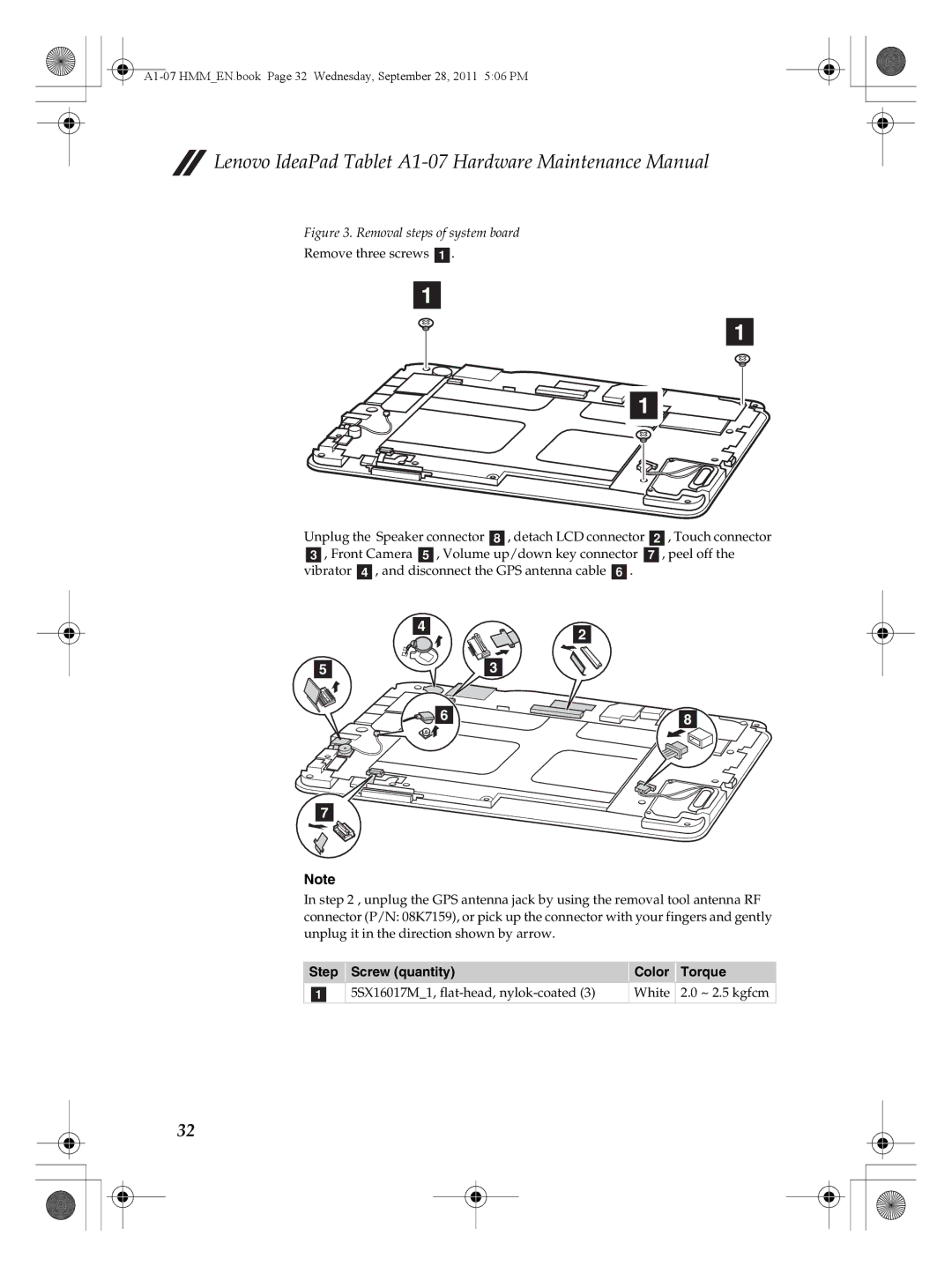
Figure 3. Removal steps of system board
Remove three screws a.
1
1
1
Unplug the Speaker connector h, detach LCD connector b, Touch connector c, Front Camera e, Volume up/down key connector g, peel off the vibrator d, and disconnect the GPS antenna cable f.
4 | 2 |
| |
5 | 3 |
6 | 8 |
7
Note
In step 2 , unplug the GPS antenna jack by using the removal tool antenna RF connector (P/N: 08K7159), or pick up the connector with your fingers and gently unplug it in the direction shown by arrow.
Step | Screw (quantity) | Color | Torque |
a | 5SX16017M_1, | White | 2.0 ~ 2.5 kgfcm |
32