ThinkPad Edge 11” and E10 Hardware Maintenance Manual
Page
ThinkPad Edge 11” and E10 Hardware Maintenance Manual
Second Edition May Copyright Lenovo 2010
Contents
Chapter 10. Parts list
iv ThinkPad Edge 11” and E10 Hardware Maintenance Manual
Chapter 9. Locations
Appendix A. Notices
About this manual
ThinkPad Edge 11 and E10
vi ThinkPad Edge 11” and E10 Hardware Maintenance Manual
Chapter 1. Safety information
General safety
Electrical safety
Safety inspection guide
Handling devices that are sensitive to electrostatic discharge
Safety notices - multilingual translations
Grounding requirements
DANGER DANGER DANGER DANGER DANGER
6 ThinkPad Edge 11” and E10 Hardware Maintenance Manual
DANGER DANGER
Chapter 1. Safety information
8 ThinkPad Edge 11” and E10 Hardware Maintenance Manual
PERIGO PERIGO PERIGO PERIGO PERIGO
10 ThinkPad Edge 11” and E10 Hardware Maintenance Manual
PERIGO PERIGO
Chapter 1. Safety information
12 ThinkPad Edge 11” and E10 Hardware Maintenance Manual
VORSICHT VORSICHT VORSICHT VORSICHT VORSICHT
14 ThinkPad Edge 11” and E10 Hardware Maintenance Manual
VORSICHT VORSICHT
Chapter 1. Safety information
16 ThinkPad Edge 11” and E10 Hardware Maintenance Manual
Chapter 1. Safety information
18 ThinkPad Edge 11” and E10 Hardware Maintenance Manual
Chapter 1. Safety information
20 ThinkPad Edge 11” and E10 Hardware Maintenance Manual
Chapter 1. Safety information
22 ThinkPad Edge 11” and E10 Hardware Maintenance Manual
Chapter 2. Important service information
Strategy for replacing FRUs
Before replacing parts
3. Select Downloads and drivers
How to use error message
Strategy for replacing a hard disk drive
Important notice for replacing a system board
Strategy for replacing FRUs for CTO, CMV, and GAV Product definition
FRU identification for CTO, CMV, and GAV products
Using PEW
Using eSupport
Using the HMM
26 ThinkPad Edge 11” and E10 Hardware Maintenance Manual
Chapter 3. General checkout
What to do first
Only certified trained personnel should service the computer
When you replace FRUs, use new nylon-coated screws
The following are not covered under warranty
Diagnostics using PC-Doctor for DOS
Checkout guide
Testing the computer
The options on the test menu are as follows
Lenovo ThinkVantage Toolbox
Detecting system information with PC-Doctor
Windows
Windows XP
Table 1. FRU tests
FRU tests
The following table shows the test for each FRU
Power system checkout
Checking the ac adapter
Checking operational charging
Voltage V dc
Checking the battery pack
Checking the backup battery
If the voltage is correct, replace the system board
If the voltage is not correct, replace the backup battery
Wire
36 ThinkPad Edge 11” and E10 Hardware Maintenance Manual
Chapter 4. Related service information
Restoring the factory contents by using Recovery Disc Set
Service Web site
Operating System Recovery Disc one disc
Hard-disk password
Passwords
Power-on password
Supervisor password
How to remove the power-on password
How to remove the hard-disk password
B If an SVP has been set and is known by the service technician
Power management
Screen blank mode
Sleep or standby mode
6. Select Master HDP
Symptom-to-FRU index
Hibernation mode
Numeric error codes
Table 2. Numeric error codes
Table 2. Numeric error codes continued
Error messages
No-beep symptoms
LCD-related symptoms
Table 3. Error messages
Table 5. LCD-related symptoms
Intermittent problems
Undetermined problems
5. Determine whether the problem has been solved
a. System board b. LCD assembly
46 ThinkPad Edge 11” and E10 Hardware Maintenance Manual
i. PC Cards 4. Turn on the computer
Chapter 5. Status indicators
Table 6. Status indicators
Indicator
Meaning
Table 6. Status indicators continued
Power status
Chapter 6. Fn key combinations
Table 7. Fn key combinations
Key combination
Description
Table 7. Fn key combinations continued
Chapter 6. Fn key combinations
52 ThinkPad Edge 11” and E10 Hardware Maintenance Manual
External CRU statement to customers
Chapter 7. FRU replacement notices
Screw notices
3. Select 2. Read S/N data from EEPROM
Retaining serial numbers
Restoring the serial number of the system unit
Chapter 7. FRU replacement notices
Retaining the UUID
Reading or writing the ECA information
56 ThinkPad Edge 11” and E10 Hardware Maintenance Manual
Chapter 8. Removing and replacing a FRU
DANGER
Before servicing ThinkPad Edge 11”
1010 Battery pack
Important notice for replacing a battery pack
1020 Bottom door
For access, remove this FRU “1010 Battery pack” on page
60 ThinkPad Edge 11” and E10 Hardware Maintenance Manual
Table 9. Removal steps of bottom door
Note Applying labels to the bottom door
1030 Hard disk drive HDD
Make sure that the HDD connector is attached firmly
Table 10. Removal steps of HDD continued
1040 DIMM
Table 11. Removal steps of DIMM
1050 PCI Express Mini Card for wireless LAN
Table 12. Removal steps of PCI Express Mini Card for wireless LAN
66 ThinkPad Edge 11” and E10 Hardware Maintenance Manual
1060 PCI Express Mini Card for wireless WAN
Table 13. Removal steps of PCI Express Mini Card for wireless WAN
Table 14. Removal steps of keyboard
1070 Keyboard
68 ThinkPad Edge 11” and E10 Hardware Maintenance Manual
Table 14. Removal steps of keyboard continued
Table 15. Installation steps of keyboard
When installing the keyboard, do as follows
1. Attach the keyboard connectors
70 ThinkPad Edge 11” and E10 Hardware Maintenance Manual
Chapter 8. Removing and replacing a FRU
72 ThinkPad Edge 11” and E10 Hardware Maintenance Manual
M2 × 2 mm, big-head, nylon-coated
74 ThinkPad Edge 11” and E10 Hardware Maintenance Manual
1090 Bluetooth daughter card BDC-2
Table 17. Removal steps of BDC-2
1100 I/O board
Table 18. Removal steps of I/O board
Important notices for handling the system board
1110 Speaker assembly
1120 System board, fan assembly, and backup battery
PCH Platform Controller Hub
For Intel models
Accelerometer chip for the HDD Active Protection System CPU
CPU South Bridge
For AMD models
Accelerometer chip for the HDD Active Protection System North Bridge
80 ThinkPad Edge 11” and E10 Hardware Maintenance Manual
Chapter 8. Removing and replacing a FRU
82 ThinkPad Edge 11” and E10 Hardware Maintenance Manual
For AMD models For Intel models
1130 LCD unit
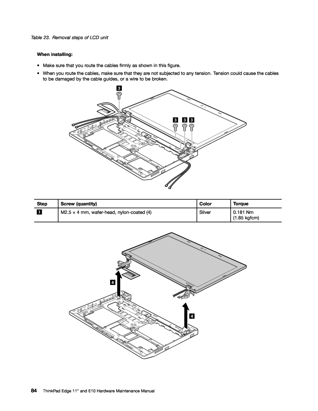
Table 22. Removal steps of LCD unit
84 ThinkPad Edge 11” and E10 Hardware Maintenance Manual
Table 23. Removal steps of LCD unit
Table 24. Removal steps of CRT board assembly with cable
1140 CRT board assembly with cable
1150 DC-in cable and base cover assembly
Note Applying labels to the base cover
Chapter 8. Removing and replacing a FRU
2010 LCD bezel assembly
Table 26. Removal steps of LCD bezel assembly
88 ThinkPad Edge 11” and E10 Hardware Maintenance Manual
Step
2020 Integrated camera
For access, remove these FRUs, in order “1010 Battery pack” on page
“2010 LCD bezel assembly” on page
Table 27. Removal steps of integrated camera
2030 LCD panel, hinges, and LCD cable
Table 28. Removal steps of LCD panel, hinges, and LCD cable
Table 28. Removal steps of LCD panel, hinges, and LCD cable continued
92 ThinkPad Edge 11” and E10 Hardware Maintenance Manual
2040 Antenna kit and LCD rear cover assembly
Table 29. Removal steps of antenna kit and LCD rear cover assembly
94 ThinkPad Edge 11” and E10 Hardware Maintenance Manual
Chapter 9. Locations
Front view
Rear view
Bottom view
Combo audio jack RJ-45 Ethernet connector
Universal serial bus USB connectors Security keyhole
Chapter 10. Parts list
Overall
98 ThinkPad Edge 11” and E10 Hardware Maintenance Manual
FRU no
Table 30. Parts list-Overall
FRU Overall
Table 30. Parts list-Overall continued
100 ThinkPad Edge 11” and E10 Hardware Maintenance Manual
FRU no
102 ThinkPad Edge 11” and E10 Hardware Maintenance Manual
FRU no
LCD FRUs
104 ThinkPad Edge 11” and E10 Hardware Maintenance Manual
Table 31. Parts list-LCD FRUs
FRU LCD FRUs
Table 31. Parts list-LCD FRUs continued
106 ThinkPad Edge 11” and E10 Hardware Maintenance Manual
Keyboard
Table 32. Parts list-Keyboard
AC adapters
Miscellaneous parts
Table 33. Parts list-2-pin ac adapters
Table 34. Parts list-3-pin ac adapters
Table 37. Parts list-3-pin power cords
Power cords
Table 36. Parts list-2-pin power cords
Recovery discs Windows 7 Home Basic 32 bit DVDs
Windows 7 Home Premium 32 bit DVDs
Windows 7 Home Premium 64 bit DVDs
Windows 7 Professional 64 bit DVDs
0328-CTO, 3Sx, 3Tx 2545-CTO, 2Cx, 2Dx, 2Fx, 2Gx, 33x, 34x
Windows 7 Starter 32 bit DVDs
Table 42. Parts list-Windows 7 Starter 32 bit recovery DVDs
Common service tools
Table 43. Parts list-Common service tools
Morrisville, NC U.S.A Attention Lenovo Director of Licensing
Appendix A. Notices
Lenovo United States, Inc 1009 Think Place - Building One
Electronic emission notices
Trademarks
Page
75Y692501
Part Number 75Y692501 Printed in China 1P P/N 75Y692501