Manuals
/
Lenox
/
Household Appliance
/
Heat Pump
Lenox
50677201, Elite Series XP14 Units HEAT PUMPS Typical Unit Wiring Diagram
Models:
50677201
Elite Series XP14 Units HEAT PUMPS
1
20
32
32
Download
32 pages
14.37 Kb
17
18
19
20
21
22
23
24
Install
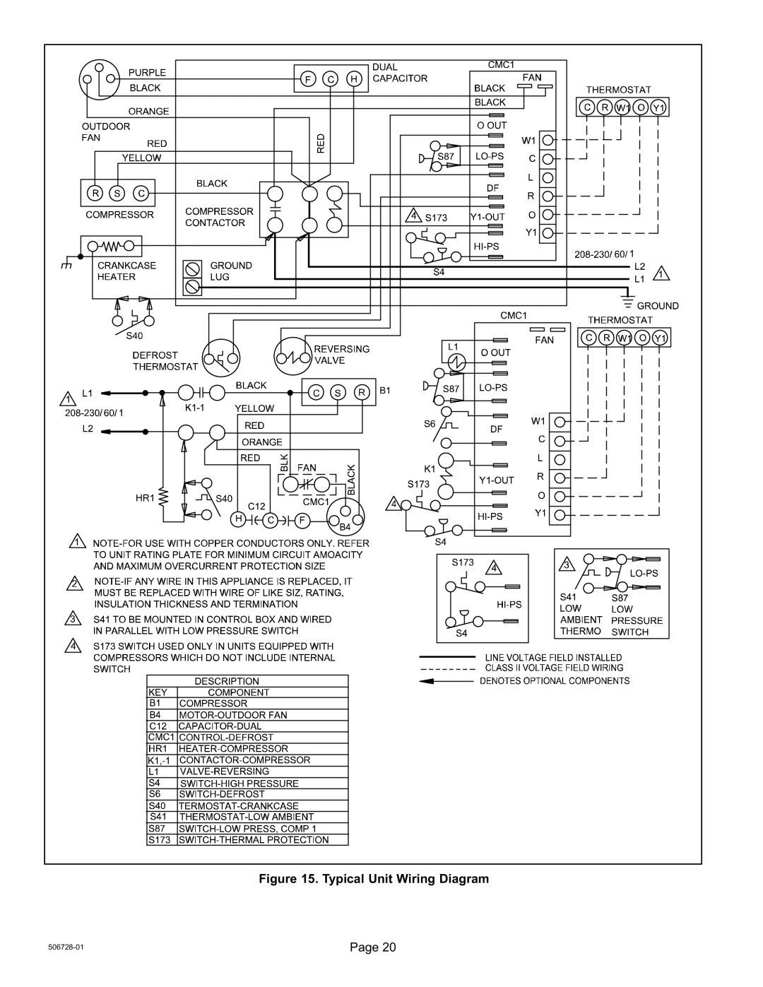
Typical Unit Wiring Diagram
Dimension
Maintenance
Optimizing Procedure
3RECOVERING Refrigerant
New Outdoor Unit Placement
Wrap Service Valves
Using Feet Extenders
Page 20
Image 20
Figure 15. Typical Unit Wiring Diagram
506728−01
Page 20
Page 19
Page 21
Page 20
Image 20
Page 19
Page 21
Contents
General
Table of Contents
Shipping and Packing List
Unit Dimensions Inches mm
Model Number Identification 14 −036 − 230 −
Side View
TOP View
Control Panel
PLUMBING, Switches Sensor Components
Typical Unit Parts Arrangement
Operating Gauge Set and Service Valves
Caps and Fasteners Torque Requirements
11 12
Recovering Refrigerant from Existing System
1DISCONNECT Power
3RECOVERING Refrigerant
Method Method 2 Limitations
New Outdoor Unit Placement
Detail a Outside Unit Placement
Using Feet Extenders
Elevated Slab Mounting
Detail D Slab Side Mounting
Louvered Panel Removal
Removing and Installing Panels
Louvered Panel Installation
NEW or Replacement Line SET Installation
Using Existing Line SET
Line Set Requirements
Adding Polyol Ester OIL Requirements
Refrigerant Line SET From Vertical to Horizontal
Refrigerant Line SET Alling Horizontal Runs
Brazing Connections
1CUT and Debur
2CAP and Core Removal
Wrap Service Valves
Flow Nitrogen
6BRAZE Line SET
Preparation for Next Step
2CONNECT Gauges and Equipment for Flushing Procedure
Installing New Indoor Metering Device
Indoor Expansion Valve Installation
Sensing Bulb Installation
Equalizer Line Installation
Manifold Gauge Set Connections for Leak Testing
Leak Test Line Set and Indoor Coil
Evacuating Line Set and Indoor Coil
Evacuating Line Set and Indoor Coil
Size Circuit and Install Disconnect
2INSTALL Thermostat
Electrical
24VAC Transformer
Typical Unit Wiring Diagram
Typical Factory Wiring Copeland Compressor
Typical Factory Wiring Interlink Compressor
Unit Start−Up
Unit START−UP
Leak CHECK, Repair and Evacuate
Connect Manifold Gauge SET and WEIGH−IN Charge
Refrigerant Charge per Line Set Length
Connections for Optimizing System Charge
Calculating System Charge for Outdoor Unit Void of Charge
Adjusting Indoor Airflow
Optimizing Procedure
Temperature rise F
Optimizing System Refrigerant Charge
SATº LIQº SCº =
Normal Operating Pressures − Liquid +10 and Vapor +5 Psig
CBX32MV−018/024 CX34−31
Defrost System
Defrost Control CMC1
Maintenance
Defrost Control CMC1 Diagnostic LED
Dealer
Homeowner
XP14 Series
Start−Up and Performance Checklist
Installer City
Job Name Job no Date Job Location City
Sequence of Operation Thermostat
Top
Page
Image
Contents