New Outdoor Unit Placement
| CAUTION |
| ELEVATING THE UNIT |
|
| ||
|
| Units are outfitted with elongated support feet as illustrated | |||||
|
|
|
|
| in figure 6, detail C. |
|
|
In order to avoid injury, take proper precaution when lift- |
|
| |||||
|
|
|
| ||||
ing heavy objects. |
| If additional elevation is necessary, raise the unit by | |||||
|
|
|
|
| extending the height of the unit support feet. This may be | ||
|
|
|
| ||||
Remove existing outdoor unit prior to placement of new |
| achieved by using a 2 inch (50.8mm) schedule 40 female | |||||
| threaded adapter. |
|
| ||||
outdoor unit. See Unit Dimensions on page 2 for sizing |
|
|
| ||||
|
|
|
| ||||
mounting slab, platforms or supports. Refer to figure 5 for |
| NOTE eep the height of ext | enders short enough to | ||||
mandatory installation clearance requirements. |
| ensure a sturdy installation. If it is necessary to extend | |||||
|
|
|
|
| further, consider a different type of field−fabricated | ||
POSITIONING CONSIDERATIONS |
| framework that is sturdy enough for greater heights. | |||||
Consider the following when positioning the unit: |
| ROOF MOUNTING |
|
| |||
S Some localities are adopting sound ordinances based |
|
|
| ||||
| Install the unit a minimum of 6 inches (152 mm) above the | ||||||
on the unit’s sound level registered from the adjacent |
| ||||||
| roof surface to avoid ice build−up around the unit. Locate | ||||||
property, not from the installation property. Install the |
| ||||||
| the unit above a load bearing wall or area of the roof that | ||||||
unit as far as possible from the property line. |
| ||||||
| can adequately support the unit. Consult local codes for | ||||||
S When possible, do not install the unit directly outside |
| ||||||
| rooftop applications. See figure 6, detail F for other roof top | ||||||
a window. Glass has a very high level of sound |
| ||||||
| mounting considerations. |
|
| ||||
transmission. For proper placement of unit in relation |
|
|
| ||||
|
|
|
| ||||
to a window see the provided illustration in figure 6, |
|
|
|
| |||
| NOTICE | ||||||
detail A. |
| ||||||
|
|
|
| ||||
PLACING UNIT ON SLAB |
|
|
|
| |||
| Roof Damage! |
|
| ||||
When installing unit at grade level, the top of the slab |
| This system contains both refrigerant and oil. Some | |||||
should be high enough above grade so that water from |
| ||||||
| rubber roofing material may absorb oil and cause the | ||||||
higher ground will not collect around the unit. The slab |
| ||||||
| rubber to swell when it comes into contact with oil. The | ||||||
should have a slope tolerance as described in figure 6, |
| ||||||
| rubber will then bubble and could cause leaks. Protect | ||||||
detail B. |
| ||||||
| the roof surface to avoid exposure to refrigerant and oil | ||||||
|
|
|
|
| |||
NOTE If necessary for stability, anchor unit to slab as |
| during service and installation. Failure to follow this | |||||
| notice could result in damage to roof surface. | ||||||
described in figure 6, detail D. |
| ||||||
|
|
|
|
|
|
| |
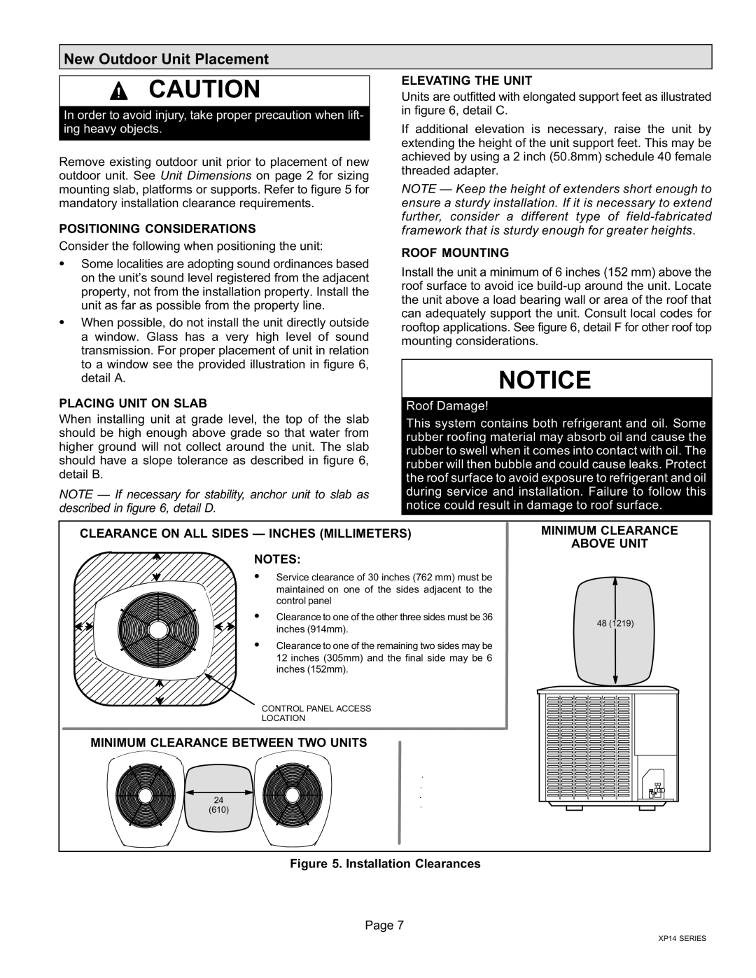
CLEARANCE ON ALL SIDES |
| MINIMUM CLEARANCE | |||||
|
| ABOVE UNIT | |||||
|
|
|
|
|
| ||
|
|
| NOTES: |
|
|
|
|
|
|
|
|
|
|
| |
|
|
|
|
|
|
| |
S Service clearance of 30 inches (762 mm) must be maintained on one of the sides adjacent to the control panel
S Clearance to one of the other three sides must be 36
inches (914mm).
48 (1219)
S Clearance to one of the remaining two sides may be 12 inches (305mm) and the final side may be 6 inches (152mm).
CONTROL PANEL ACCESS
LOCATION
MINIMUM CLEARANCE BETWEEN TWO UNITS
24
(610)
Figure 5. Installation Clearances
Page 7
XP14 SERIES