Pressure Switch Circuit
The defrost control incorporates two pressure switch circuits. The high pressure switch (S4) is
During a single demand cycle, the defrost control will lock out the unit after the fifth time that the circuit is interrupted by any pressure switch wired to the defrost control. In addition, the diagnostic LEDs will indicate a
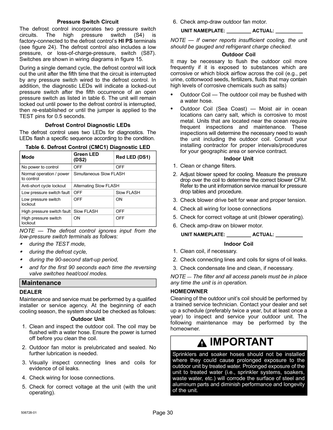
Defrost Control Diagnostic LEDs
The defrost control uses two LEDs for diagnostics. The LEDs flash a specific sequence according to the condition.
Table 6. Defrost Control (CMC1) Diagnostic LED
Mode | Green LED | Red LED (DS1) | |
(DS2) | |||
|
| ||
|
|
| |
No power to control | OFF | OFF | |
|
|
| |
Normal operation / power | Simultaneous Slow FLASH | ||
to control |
|
| |
|
| ||
Alternating Slow FLASH | |||
|
|
| |
Low pressure switch fault | OFF | Slow FLASH | |
|
|
| |
Low pressure switch | OFF | ON | |
lockout |
|
| |
|
|
| |
High pressure switch fault | Slow FLASH | OFF | |
|
|
| |
High pressure switch | ON | OFF | |
lockout |
|
| |
|
|
| |
NOTE
Sduring the TEST mode,
Sduring the defrost cycle,
Sduring the
Sand for the first 90 seconds each time the reversing valve switches heat/cool modes.
Maintenance
DEALER
Maintenance and service must be performed by a qualified installer or service agency. At the beginning of each cooling season, the system should be checked as follows:
Outdoor Unit
1.Clean and inspect the outdoor coil. The coil may be flushed with a water hose. Ensure the power is turned off before you clean the coil.
2.Outdoor fan motor is prelubricated and sealed. No further lubrication is needed.
3.Visually inspect connecting lines and coils for evidence of oil leaks.
4.Check wiring for loose connections.
5.Check for correct voltage at the unit (with the unit operating).
6. Check amp−draw outdoor fan motor.
UNIT NAMEPLATE: _________ ACTUAL: __________
NOTE s insufficient cooling, the unit
should be gauged and refrigerant charge checked. Outdoor Coil
It may be necessary to flush the outdoor coil more frequently if it is exposed to substances which are corrosive or which block airflow across the coil (e.g., pet urine, cottonwood seeds, fertilizers, fluids that may contain high levels of corrosive chemicals such as salts)
SOutdoor Coil door coil may be flushed with a water hose.
SOutdoor Coil (Sea Coast) air in ocean
locations can carry salt, which is corrosive to most metal. Units that are located near the ocean require frequent inspections and maintenance. These inspections will determine the necessary need to wash the unit including the outdoor coil. Consult your installing contractor for proper intervals/procedures for your geographic area or service contract.
Indoor Unit
1.Clean or change filters.
2.Adjust blower speed for cooling. Measure the pressure drop over the coil to determine the correct blower CFM. Refer to the unit information service manual for pressure drop tables and procedure.
3.Check blower drive belt for wear and proper tension.
4.Check all wiring for loose connections
5.Check for correct voltage at unit (blower operating).
6.Check amp−draw on blower motor.
UNIT NAMEPLATE: _________ ACTUAL: __________
Indoor Coil
1.Clean coil, if necessary.
2.Check connecting lines and coils for signs of oil leaks.
3.Check condensate line and clean, if necessary.
NOTE The filter and all access panels must be in place any time the unit is in operation.
HOMEOWNER
Cleaning of the outdoor unit’s coil should be performed by a trained service technician. Contact your dealer and set up a schedule (preferably twice a year, but at least once a year) to inspect and service your outdoor unit. The following maintenance may be performed by the homeowner.
![]() IMPORTANT
IMPORTANT
Sprinklers and soaker hoses should not be installed where they could cause prolonged exposure to the outdoor unit by treated water. Prolonged exposure of the unit to treated water (i.e., sprinkler systems, soakers, waste water, etc.) will corrode the surface of steel and aluminum parts and diminish performance and longevity of the unit.
506728−01 | Page 30 |
