20/20 AD User Guide | Controls and Connectors |
The Level Meters
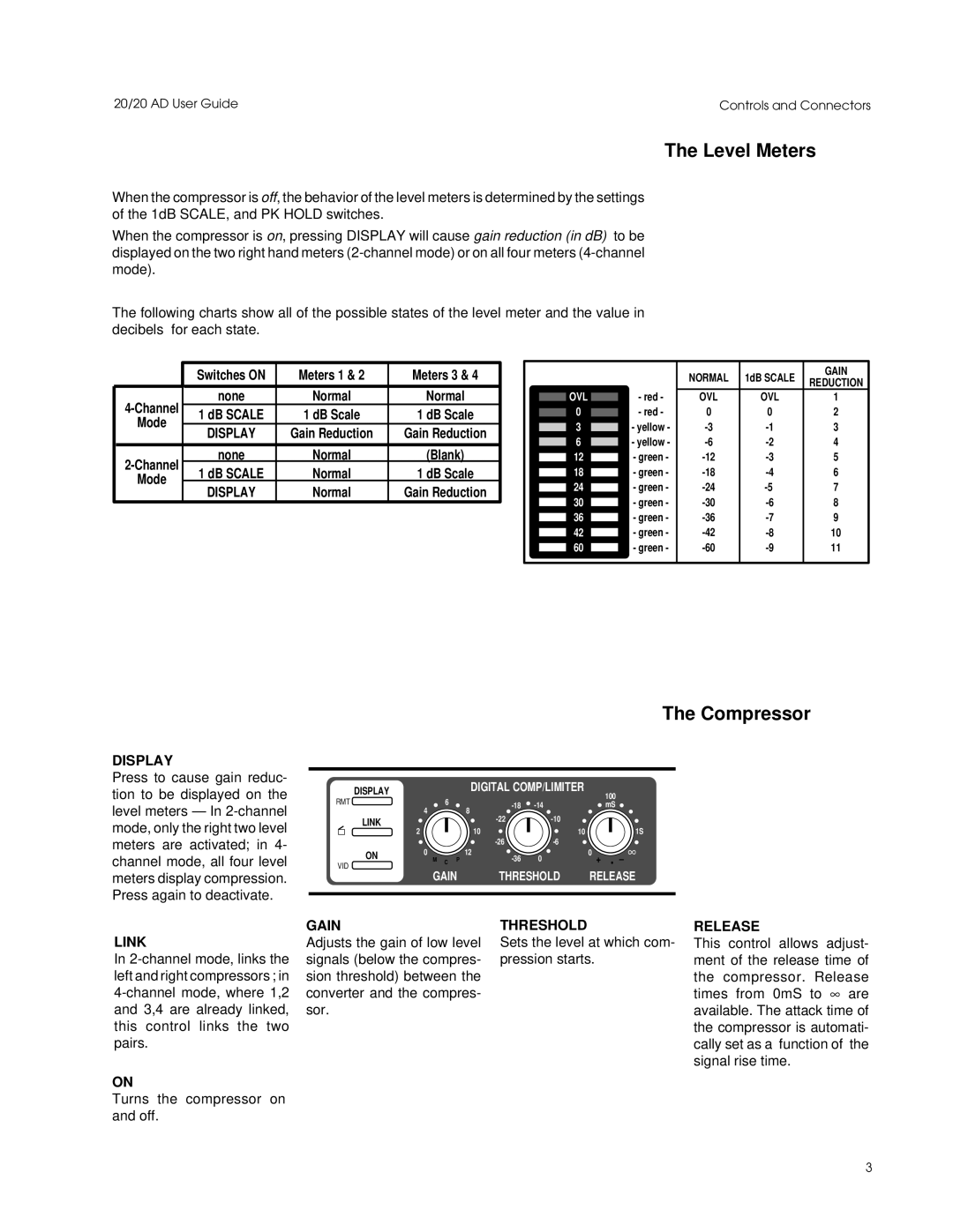
When the compressor is off, the behavior of the level meters is determined by the settings of the 1dB SCALE, and PK HOLD switches.
When the compressor is on, pressing DISPLAY will cause gain reduction (in dB) to be displayed on the two right hand meters
The following charts show all of the possible states of the level meter and the value in decibels for each state.
| Switches ON | Meters 1 & 2 | Meters 3 & 4 | |
|
|
|
| |
none | Normal | Normal | ||
1 dB SCALE | 1 dB Scale | 1 dB Scale | ||
Mode | ||||
DISPLAY | Gain Reduction | Gain Reduction | ||
| ||||
|
|
|
| |
none | Normal | (Blank) | ||
1 dB SCALE | Normal | 1 dB Scale | ||
Mode | ||||
DISPLAY | Normal | Gain Reduction | ||
|
 OVL
OVL 
0
3
6
12
18
24
30
36
42
60
- red - - red -
- yellow - - yellow - - green - - green - - green - - green - - green - - green - - green -
NORMAL | 1dB SCALE | GAIN | |
REDUCTION | |||
|
| ||
OVL | OVL | 1 | |
0 | 0 | 2 | |
3 | |||
4 | |||
5 | |||
6 | |||
7 | |||
8 | |||
9 | |||
10 | |||
11 | |||
|
|
|
The Compressor
DISPLAY
Press to cause gain reduc- tion to be displayed on the level meters — In
LINK
In
ON
Turns the compressor on and off.
|
|
| DISPLAY |
|
|
|
| DIGITAL COMP/LIMITER |
| 100 | |||||
| RMT |
|
| 6 |
|
|
|
|
| ||||||
| 4 |
| 8 |
| mS | ||||||||||
|
|
|
|
|
|
|
| ||||||||
|
|
|
|
|
|
|
|
|
|
|
| ||||
|
|
| LINK | 2 |
|
|
| 10 |
|
|
|
| 1S | ||
|
|
|
|
|
|
|
|
|
| ||||||
|
|
|
|
|
|
|
|
| 10 |
|
|
| |||
|
|
|
|
|
|
|
|
|
|
| |||||
|
|
|
|
|
|
|
|
|
|
|
| ∞ | |||
|
|
| ON | 0 |
|
|
| 12 | 0 | 0 |
|
| |||
|
|
|
| M | C | P | + |
| • – | ||||||
| VID |
|
|
|
|
|
|
| |||||||
|
|
|
|
| GAIN | THRESHOLD | RELEASE | ||||||||
|
|
|
|
|
|
|
|
|
|
|
|
|
|
| |
GAIN |
|
|
|
|
| THRESHOLD |
|
|
|
| |||||
Adjusts the gain of low level | Sets the level at which com- | ||||||||||||||
signals (below the compres- | pression starts. |
|
|
| |||||||||||
sion threshold) between the |
|
|
|
|
|
|
| ||||||||
converter and the compres- |
|
|
|
|
|
|
| ||||||||
sor. |
|
|
|
|
|
|
|
|
|
|
|
| |||
RELEASE
This control allows adjust- ment of the release time of the compressor. Release times from 0mS to ∞ are available. The attack time of the compressor is automati- cally set as a function of the signal rise time.
3