PLASMA TV
LCD TV MODELS
LCD TV
OWNER’S MANUAL
Downloaded From TV-Manual.com Manuals
Protection Cover
ACCESSORIES
This feature is not available for all models Polishing Cloth
Power Cord
WATCHING TV / PROGRAMME CONTROL
CONTENTS
EXTERNAL EQUIPMENT SETUP
PREPARATION
APPENDIX
TIME SETTING
SOUND & LANGUAGE CONTROL
DIGITAL TELETEXT
PLASMA TV Models 42/50PG10
PREPARATION
FRONT PANEL CONTROLS
PLASMA TV Models 42/50PG20**, 42/50/60PG30
Attaching the TV to a desk Only 26/32/42LG30**, 32/42LG50
LCD TV Models 26/32/37/42LG30**, 32/37/42/47/52LG50
INPUT MENU OK - +
PREPARATION
LCD TV Models 19/22LG30
LCD TV Models 19/22LS4D
BACK PANEL INFORMATION
PLASMA TV Models 42/50PG10**, 42/50PG20**, 42/50/60PG30
Only 42/50PG10
LCD TV Models 19/22/26/32/37/42LG30** 32/37/42/47/52LG50
PREPARATION
AV 1 AV
LCD TV Models 19/22LS4D
PREPARATION
STAND INSTALLATION
LCD TV Models 26/32/37/42LG30**, 32/37/42LG50
Only 19/22LG30
PREPARATION
Only 42PG10**, 42PG20**, 42PG30
3 Fix the 4 bolts securely using the holes in the back of the TV
2 Assemble the TV as shown
PREPARATION
STAND INSTALLATION Only 19/22LS4D
Swivel Stand
Except for 19/22LS4D*, 50PG10
DETACHING STAND Only 19/22LS4D
2 Pull the Cover Base backward during pressing
5 Pull stand body to separate from the TV during
PREPARATION
PLEASE SET IT UP CAREFULLY SO THE PRODUCT DOES NOT FALL OVER
Only 42/50PG10
BACK COVER FOR WIRE ARRANGEMENT
How to remove the cable management clip
PLASMA TV Models
LCD TV Models 19/22LS4D
How to remove the cable management clip LCD TV Models 19/22LS4D
LCD TV Models 26/32/37/42LG30** 32/37/42/47/52LG50
PREPARATION
LCD TV Models 19/22LG30
How to remove the cable management clip
PREPARATION
POSITIONING YOUR DISPLAY Only 19/22LG30**, 19/22LS4D
LOCATION Only 19/22LG30**, 19/22LS4D
KENSINGTON SECURITY SYSTEM Only 19/22LG30**, 19/22LS4D
EARTHING
DESKTOP PEDESTAL INSTALLATION
WALL MOUNT HORIZONTAL INSTALLATION
Not using the desk-type stand
Antenna
ANTENNA CONNECTION
PREPARATION
Outdoor Antenna
Connecting a set-top box with an HDMI cable
EXTERNAL EQUIPMENT SETUP
HD RECEIVER SETUP
Connecting with a component cable
Except for 19/22LS4D
EXTERNAL EQUIPMENT SETUP
DIGITAL AUDIO OUT SETUP
Connecting with a HDMI to DVI cable
Component Input ports
DVD SETUP
When connecting with a component cable
Connecting with a Euro Scart cable
EXTERNAL EQUIPMENT SETUP
Connecting with a S-Video cable
Connecting the HDMI cable
Except for 19/22LS4D*, 42/50PG10
Antenna
VCR SETUP
When connecting with a RF Cable
Wall Jack
Select AV1 input source using the INPUT button on
Connecting with a RCA cable
EXTERNAL EQUIPMENT SETUP
Connecting with a Euro Scart cable
Except for 19/22LS4D*, 42/50PG10
OTHER A/V SOURCE SETUP
Camcorder
Connecting with a S-Video cable
EXTERNAL EQUIPMENT SETUP
PC SETUP
Connecting with a D-sub 15 pin cable
INSERTION OF CI MODULE
Connecting with a HDMI to DVI cable
G To enjoy vivid picture and sound, connect a PC to the TV
Downloaded From TV-Manual.com Manuals
Resolution
Supported Display Resolution Only 19/22LS4D
EXTERNAL EQUIPMENT SETUP
Resolution
Resolution
Supported Display Resolution
Only 19/22/26/32/37/42LG30**, 32/37/42/47/52LG50
Resolution
Select Reset
Screen Setup for PC mode
Screen Reset
EXTERNAL EQUIPMENT SETUP
SCREEN
Adjustment for screen Position, Size, Phase
Select Position, Size or Phase
PICTURE
Select the desired resolution
Selecting Resolution
EXTERNAL EQUIPMENT SETUP
Select Resolution
SCREEN
Auto Configure RGB PC mode only
Select Auto Config
PICTURE
WATCHING TV / PROGRAMME CONTROL
REMOTE CONTROL KEY FUNCTIONS Only 19/22LS4D
LIST
Installing Batteries
Only 42/50PG10
WATCHING TV / PROGRAMME CONTROL
control buttons
Installing Batteries
Except for 19/22LS4D*, 42/50PG10
WATCHING TV / PROGRAMME CONTROL
RATIO
Installing Batteries
Initializing setup
VOLUME ADJUSTMENT
TURNING ON THE TV
PROGRAMME SELECTION
AUDIO
ON SCREEN MENUS SELECTION AND ADJUSTMENT
TIME
OPTION
WATCHING TV / PROGRAMME
AUTO PROGRAMME TUNING
Select Auto Tuning
WATCHING TV / PROGRAMME CONTROL
Use NUMBER buttons to input a 4-digit password in Lock System ‘On’
MANUAL PROGRAMME TUNING IN DIGITAL MODE
SETUP
Select SETUP
Select the desired
MANUAL PROGRAMME TUNING IN ANALOGUE MODE
SETUP
WATCHING TV / PROGRAMME CONTROL
Select Manual Tuning
A Fine Tuning
A Assigning a station name
Select SETUP
PROGRAMME EDIT
WATCHING TV / PROGRAMME CONTROL
Programme Edit
IN DTV/RADIO MODE
A Skipping a programme number
A Selecting favourite programme
YELLOW
IN TV MODE
WATCHING TV / PROGRAMME CONTROL
Start Auto Sort
Select Booster
BOOSTER IN DIGITAL MODE ONLY
Select SETUP
Software Update Off
WATCHING TV / PROGRAMME CONTROL
SOFTWARE UPDATE
When setting “Software Update”
SETUP
Display the information of Channel
DIAGNOSTICS IN DIGITAL MODE ONLY
Select SETUP
Select Diagnostics
CI COMMON INTERFACE INFORMATION
WATCHING TV / PROGRAMME CONTROL
CI Information
A Paging through a programme list
SELECTING THE PROGRAMME TABLE
A Displaying programme LIST
A Selecting a programme in the programme list
OPTION
WATCHING TV / PROGRAMME CONTROL
Except for 19/22LS4D*, 42/50PG10
OPTION
When a device is connected displayed in bright colour
SIMPLINK Functions
SIMPLINK Menu
When no device is connect- ed displayed in gray
OPTION
INPUT LABEL
WATCHING TV / PROGRAMME CONTROL
OPTION
OffCinema GameSport
AV MODE
Manual Timer
EPG ELECTRONIC PROGRAMME GUIDE IN DIGITAL MODE
Switch on/off EPG
Select a programme
PROGRAMME GUIDE
Button Function in NOW/NEXT Guide Mode
Button Function in 8 Day Guide Mode
Button Function in Date Change Mode
Button Function in Extended Description Box
EPG ELECTRONIC PROGRAMME GUIDE IN DIGITAL MODE
Button Function in Record/Remind Setting Mode
Button Function in Schedule List Mode
PICTURE CONTROL
PICTURE SIZE ASPECT RATIO CONTROL
PICTURE CONTROL
Original
Just Scan
Select PICTURE
PRESET PICTURE SETTINGS
Picture Mode-Preset
Select Picture Mode
Picture Mode Vivid
Auto Colour Tone Control Warm/Medium/Cool
Select Colour Temperature
Picture Mode Vivid
Picture Mode-User option
MANUAL PICTURE ADJUSTMENT
PICTURE
Picture Mode-Expert Control
Select Picture Mode
PICTURE CONTROL
Noise Reduction
PICTURE IMPROVEMENT TECHNOLOGY
Fresh Contrast
Fresh Colour
Picture Mode Vivid
ADVANCED - FILM MODE
Select Film Mode
Picture Mode Vivid
ADVANCED - BLACKDARKNESS LEVEL
PICTURE
PICTURE
Film Mode
EYE CARE LCD TV ONLY
Picture Mode Vivid
Picture Mode Vivid
Resetting video configuration
PICTURE RESET
Initialize the adjusted value
Select Picture Reset
OPTION
IMAGE STICKING MINIMIZATION ISM METHOD
PLASMA TV ONLY
PICTURE CONTROL
OPTION
POWER SAVING PICTURE MODE PLASMA TV ONLY
Power Saving
Factory Reset
AUDIO
AUTO VOLUME LEVELER
SOUND & LANGUAGE CONTROL
Select Auto Volume
Standard
PRESET SOUND SETTINGS-SOUND MODE
AUDIO
AUDIO
Sound Mode
SOUND SETTING ADJUSTMENT -USER MODE
SOUND & LANGUAGE CONTROL
Sound Mode
Select Balance
BALANCE
Make desired adjustment
Select AUDIO
Select AUDIO
TV SPEAKERS ON/ OFF SETUP
SOUND & LANGUAGE CONTROL
Except for 19/22LS4D
SELECTING DIGITAL AUDIO OUT
AUDIO
AUDIO
SOUND & LANGUAGE CONTROL
AUDIO RESET
Initialize the adjusted value
Resetting sound mode configuration
I/II
Stereo/Dual Reception In Analogue Mode Only
NICAM Reception In Analogue Mode Only
Speaker Sound Output Selection
SOUND & LANGUAGE CONTROL
Save
ON-SCREEN MENU LANGUAGE COUNTRY SELECTION
Select OPTION
Select Menu Language or Country
LANGUAGE SELECTION IN DIGITAL MODE ONLY
SOUND & LANGUAGE CONTROL
Hearing
TIME
TIME SETTING
CLOCK SETUP
TIME
TIME
TIME SETTING
AUTO ON/OFF TIMER SETTING
TIME
Press the MENU button to return to normal TV viewing
AUTO SHUT-OFF SETTING
TIME
Select Off or On
TIME ZONE SETUP
SLEEP TIMER SETTING
TIME SETTING
0 Be sure to remember this number! Re-enter new password for confirm
SET PASSWORD & LOCK SYSTEM
PARENTAL CONTROL / RATINGS
Input a 4-digit password
Select LOCK
PARENTAL CONTROL / RATINGS
BLOCK PROGRAMME
LOCK
LOCK
PARENTAL CONTROL IN DIGITAL MODE ONLY
Make appropriate adjustments
LOCK
OPTION
KEY LOCK
PARENTAL CONTROL / RATINGS
OPTION
TOP TEXT
SWITCH ON/OFF
TELETEXT
SIMPLE TEXT
TELETEXT
FASTEXT
SPECIAL TELETEXT FUNCTIONS
TELETEXT WITHIN DIGITAL SERVICE
TELETEXT IN DIGITAL SERVICE
DIGITAL TELETEXT
OPTION
Initializing Reset to original factory settings
APPENDIX
OPTION
TROUBLESHOOTING
The TV does not operate properly
The video function does not work
APPENDIX
There is a problem in PC mode. Only PC mode applied
The audio function does not work
Extended Absence
MAINTENANCE
Cleaning the Screen
Cleaning the Cabinet
42PG3000-ZA
PRODUCT SPECIFICATIONS
APPENDIX
Downloaded From TV-Manual.com Manuals
19LG30 19LG3000-ZA
Downloaded From TV-Manual.com Manuals
32LG5000-ZA
APPENDIX
Downloaded From TV-Manual.com Manuals
MODELS
PROGRAMMING THE REMOTE CONTROL
Programming a code into a remote mode
Only 19/22/26/32/37/42LG30**, 32/37/42/47/52LG50
Codes
HDSTB
APPENDIX
Brand
IR CODES
1. How to Connect
2. Remote Control IR Codes
A Configuration of frame
Downloaded From TV-Manual.com Manuals
APPENDIX
Code Hexa
Function
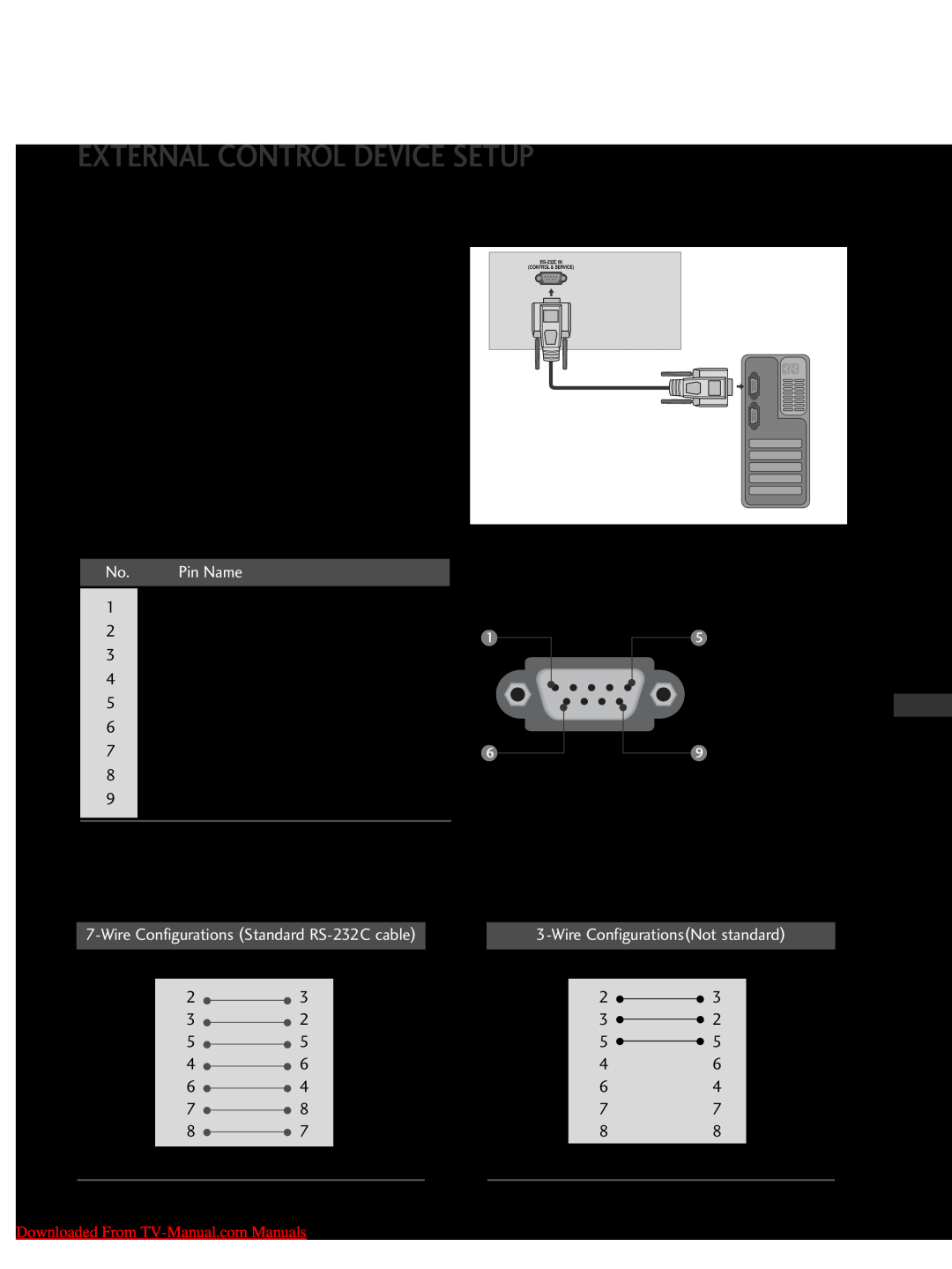
RS-232C Configurations
EXTERNAL CONTROL DEVICE SETUP
RS-232C Setup
Type of Connector D-Sub 9-Pin Male
APPENDIX
Set ID
adjust Set ID to choose the desired TV ID number
Power Indicator
A Data length 8 bits
Communication Parameters
A Baud rate 9600 bps UART
A Stop bit 1 bit
Normal screen
Data 00 Volume mute on Volume off 01 Volume mute off Volume on
APPENDIX
Downloaded From TV-Manual.com Manuals
Downloaded From TV-Manual.com Manuals
01 OSD on
01 Lock on
APPENDIX
APPENDIX
Downloaded From TV-Manual.com Manuals
Transmission
External Input
APPENDIX
Downloaded From TV-Manual.com Manuals
No. 394 - 01 88 188H, DTV No. 0 - Don’t care
Downloaded From TV-Manual.com Manuals