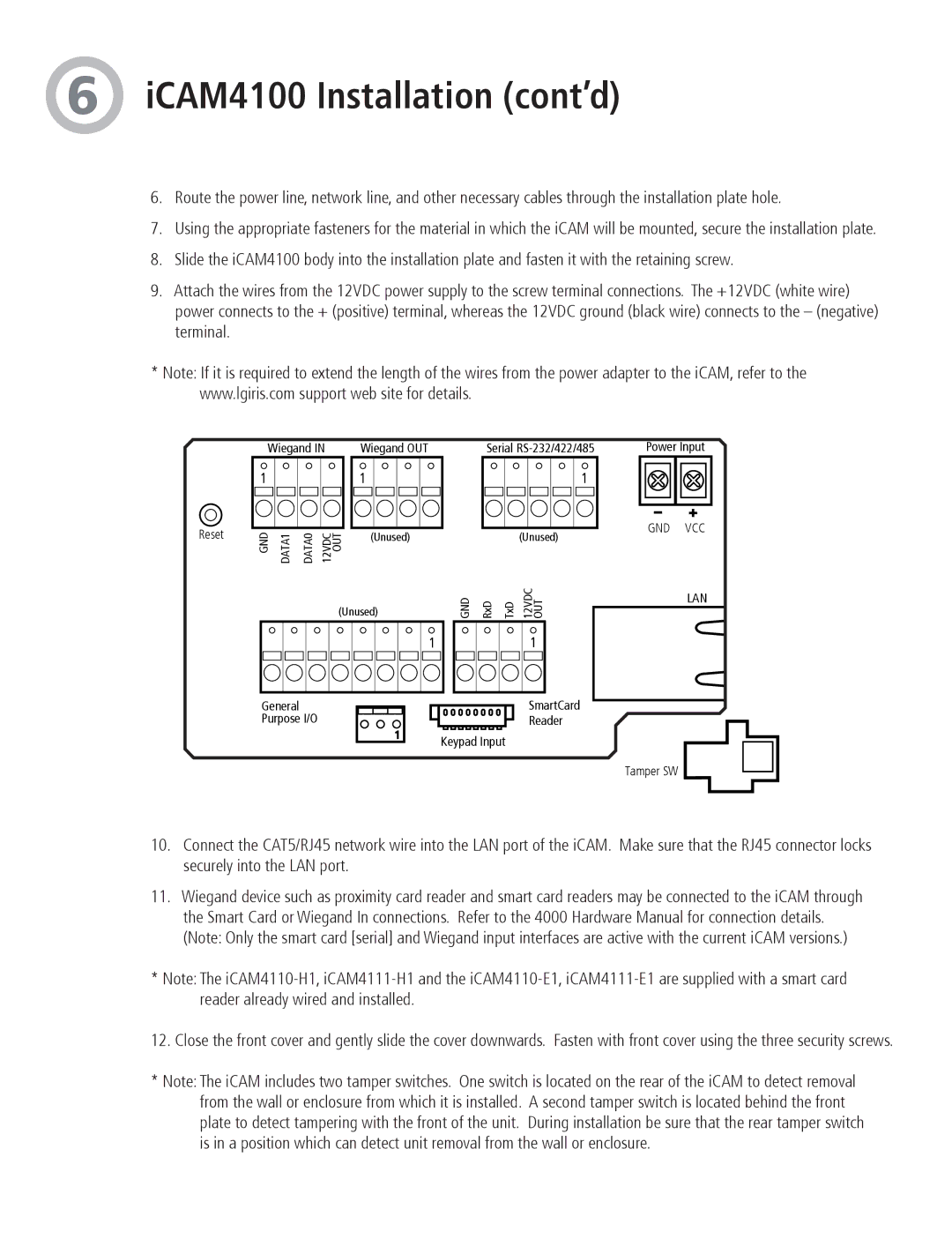
iCAM4100R, iCAM4101, iCAM4110R-E1, iCAM4110-E1, iCAM4101R specifications
LG Electronics has made a name for itself in the world of innovative technology and smart devices. Among its impressive lineup is the iCAM series, which includes the iCAM4110-H1, iCAM4110R-H1, iCAM4100, iCAM4101R, and the iCAM4110-E1. These models showcase LG's commitment to providing high-quality surveillance solutions for both residential and commercial environments.The iCAM4110-H1 and iCAM4110R-H1 are noteworthy for their robust construction and advanced imaging capabilities. Both models come equipped with high-resolution sensors, enabling users to capture clear and detailed footage, even in low-light conditions. This feature is particularly beneficial for security applications, where clarity is paramount. Additionally, they support HD video recording and offer various viewing angles, allowing for comprehensive area coverage.
The iCAM4100 and iCAM4101R models are designed for flexibility and ease of use. They feature smart connectivity options, allowing users to access their surveillance feeds remotely via smartphone or tablet. This kind of accessibility ensures users can monitor their properties in real-time, fostering peace of mind wherever they are. With integrated motion detection, notifications can be sent directly to users when activity is detected, ensuring timely responses to potential issues.
Furthermore, the iCAM4110-E1 offers enhanced features tailored to meet specific surveillance needs. This model includes advanced analytics capabilities, such as facial recognition and people counting, making it suitable for retail environments where customer behavior insights are valuable. The combination of these technologies enhances the effectiveness of security measures and operational efficiency for businesses.
All iCAM models prioritize user-friendly interfaces, making setup and operation straightforward even for those who may not be technologically inclined. With features such as weatherproofing and night vision capabilities, the iCAM series ensures reliable performance in a variety of conditions.
In summary, LG’s iCAM series presents a powerful solution for anyone looking to enhance their surveillance systems. With high-resolution imaging, smart connectivity, and advanced analytics, these models provide modern and effective ways to ensure safety and security, making them an excellent choice for both businesses and homeowners alike. Whether it's deterrence or monitoring, these cameras offer a comprehensive answer to contemporary surveillance needs.

