14. Installation
14.4 Connecting Pipings and the cable to Outdoor unit
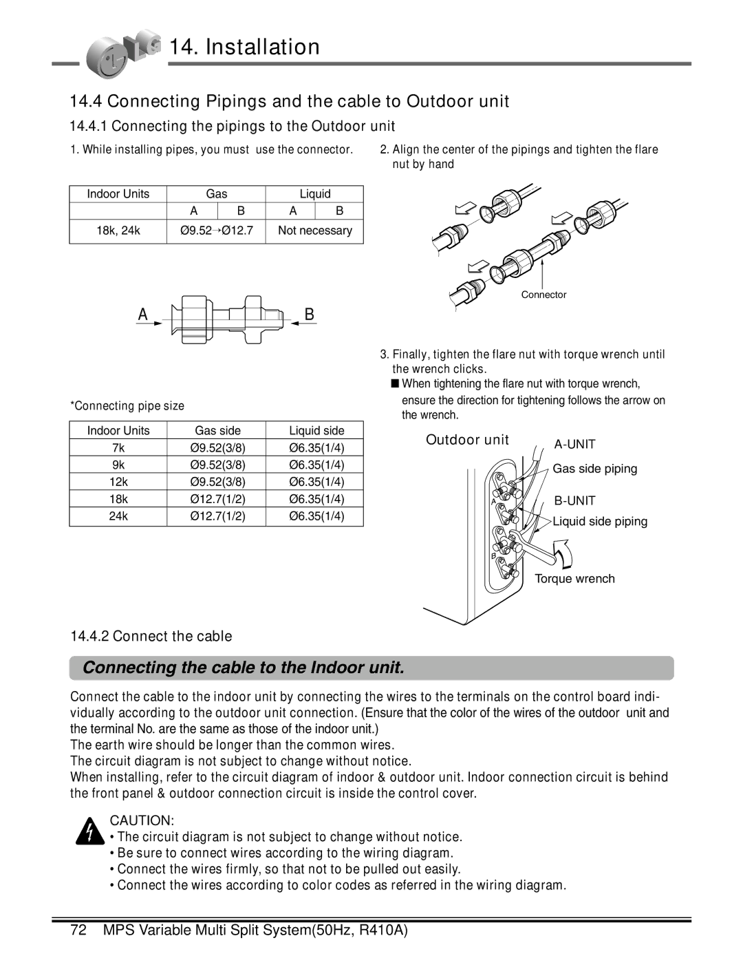
14.4.1 Connecting the pipings to the Outdoor unit
1. While installing pipes, you must use the connector.
Indoor Units |
| Gas |
| Liquid | ||
|
|
|
|
|
|
|
| A |
| B | A |
| B |
18k, 24k | Ø9.52→Ø12.7 | Not necessary | ||||
|
|
|
|
|
|
|
A ![]() B
B
*Connecting pipe size
Indoor Units | Gas side | Liquid side |
7k | Ø9.52(3/8) | Ø6.35(1/4) |
9k | Ø9.52(3/8) | Ø6.35(1/4) |
12k | Ø9.52(3/8) | Ø6.35(1/4) |
18k | Ø12.7(1/2) | Ø6.35(1/4) |
24k | Ø12.7(1/2) | Ø6.35(1/4) |
|
|
|
2.Align the center of the pipings and tighten the flare nut by hand
Connector
3.Finally, tighten the flare nut with torque wrench until the wrench clicks.
■When tightening the flare nut with torque wrench, ensure the direction for tightening follows the arrow on the wrench.
Outdoor unit | |
| |
| Gas side piping |
| |
| Liquid side piping |
Torque wrench
14.4.2 Connect the cable
Connecting the cable to the Indoor unit.
Connect the cable to the indoor unit by connecting the wires to the terminals on the control board indi- vidually according to the outdoor unit connection. (Ensure that the color of the wires of the outdoor unit and the terminal No. are the same as those of the indoor unit.)
The earth wire should be longer than the common wires. The circuit diagram is not subject to change without notice.
When installing, refer to the circuit diagram of indoor & outdoor unit. Indoor connection circuit is behind the front panel & outdoor connection circuit is inside the control cover.
CAUTION:
•The circuit diagram is not subject to change without notice.
•Be sure to connect wires according to the wiring diagram.
•Connect the wires firmly, so that not to be pulled out easily.
•Connect the wires according to color codes as referred in the wiring diagram.