Leveling Leg Assembly
To install the leveling leg assembly, complete the following:
1.Drill two
2.Adjust the leveling legs to the approximate height needed and install them on either side of the wall sleeve, using the screws provided. Bottom of wall sleeve can be anywhere from three to five inches above the screw base. Caulk around screws to prevent water leaks.
3.Level the sleeve horizontally from
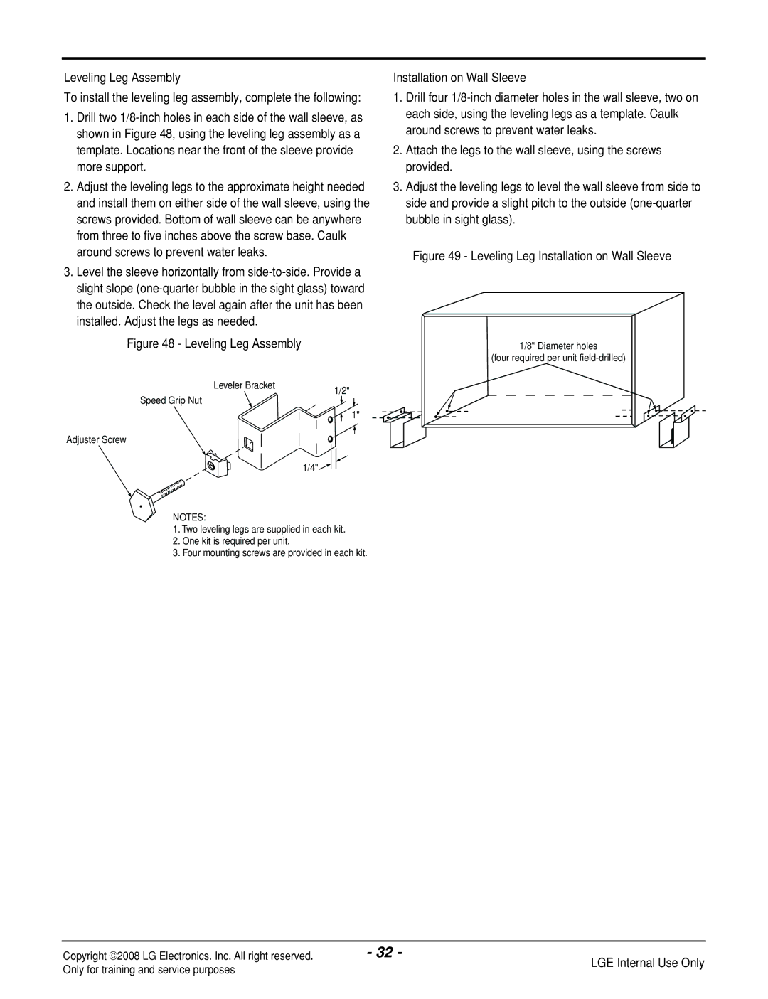
Figure 48 - Leveling Leg Assembly
Installation on Wall Sleeve
1.Drill four
2.Attach the legs to the wall sleeve, using the screws provided.
3.Adjust the leveling legs to level the wall sleeve from side to side and provide a slight pitch to the outside
Figure 49 - Leveling Leg Installation on Wall Sleeve
1/8" Diameter holes
(four required per unit
Leveler Bracket
Speed Grip Nut
Adjuster Screw
1/2"
1"
1/4"![]()
NOTES:
1.Two leveling legs are supplied in each kit.
2.One kit is required per unit.
3.Four mounting screws are provided in each kit.
Copyright ©2008 LG Electronics. Inc. All right reserved. | - 32 - |
Only for training and service purposes | LGE Internal Use Only |
|