PREPARATION
BACK PANEL INFORMATION
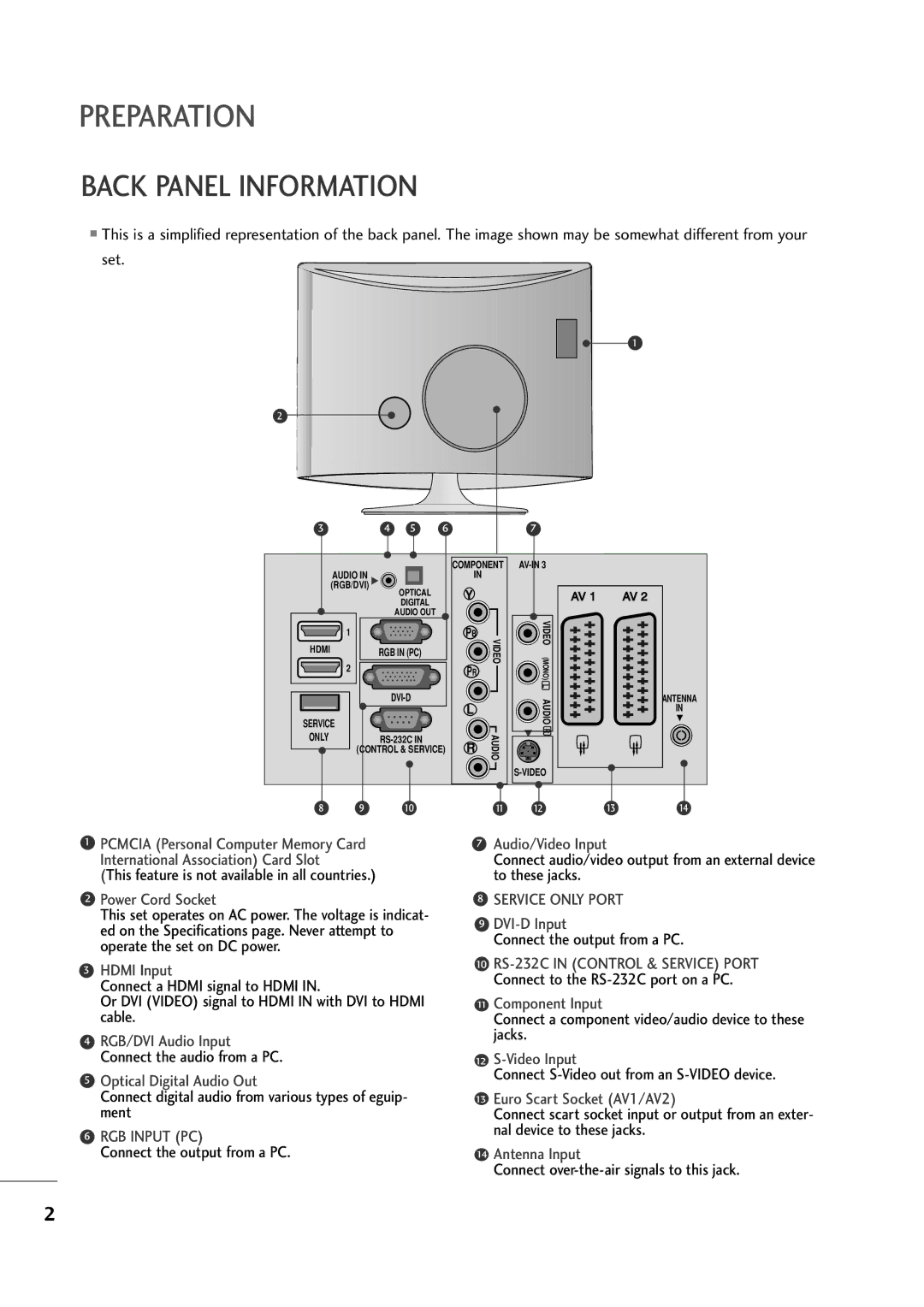
■This is a simplified representation of the back panel. The image shown may be somewhat different from your set.
1
2
3 | 4 | 5 | 6 |
7
| COMPONENT |
AUDIO IN | IN |
(RGB/DVI) |
|
|
| OPTICAL | Y |
| AV 1 |
| AV 2 |
|
| DIGITAL |
|
|
|
|
|
|
| AUDIO OUT |
|
|
|
|
|
| 1 |
| PB | VIDEO | VIDEO (MONO) |
|
|
HDMI |
| RGB IN (PC) |
|
|
| ||
| 2 |
| PR |
|
| ||
|
|
|
|
|
| ||
|
|
|
|
| L |
|
|
|
|
|
| AUDIO |
| ANTENNA | |
|
|
| L |
|
| IN | |
SERVICE |
|
|
|
|
|
| |
|
|
|
| R |
|
| |
ONLY |
|
| AUDIO |
|
| ||
| R |
|
|
| |||
| (CONTROL & SERVICE) |
|
|
| |||
|
|
|
|
|
|
| |
|
|
|
|
|
|
| |
8 | 9 | 10 |
| 11 | 12 | 13 | 14 |
1PCMCIA (Personal Computer Memory Card International Association) Card Slot
(This feature is not available in all countries.)
2Power Cord Socket
This set operates on AC power. The voltage is indicat- ed on the Specifications page. Never attempt to operate the set on DC power.
3HDMI Input
Connect a HDMI signal to HDMI IN.
Or DVI (VIDEO) signal to HDMI IN with DVI to HDMI cable.
4RGB/DVI Audio Input Connect the audio from a PC.
5Optical Digital Audio Out
Connect digital audio from various types of eguip- ment
6RGB INPUT (PC)
Connect the output from a PC.
7Audio/Video Input
Connect audio/video output from an external device to these jacks.
8SERVICE ONLY PORT
9DVI-D Input
Connect the output from a PC.
10
11Component Input
Connect a component video/audio device to these jacks.
12
Connect
13Euro Scart Socket (AV1/AV2)
Connect scart socket input or output from an exter- nal device to these jacks.
14Antenna Input
Connect
2