ART COOL MINI-SPLIT SINGLE ZONE
ELECTRICAL & REFRIGERATION • QUICK REFERENCE
Electrical Specifications
| Type | Model | BTUs | Voltage | Rated Amps | MCA* | MOP** | |
Art Cool |
|
|
| Indoor | Outdoor |
|
|
|
|
|
|
|
|
|
|
|
|
Single Zone | A/C | LA091CNP | 9,000 | 36V DC | 115 | 7.2 | 15 | 15 |
| A/C | LA121CNP | 12,000 | 36V DC | 115 | 9.3 | 15 | 20 |
| A/C | LA121CNM | 11,500 | 36V DC | 115 | 10.5 | 15 | 20 |
| A/C | LA181CNW | 18,000 | 36V DC | 230/208 | 9.8 | 15 | 20 |
|
|
|
|
|
|
|
|
|
| H/P | LA091HNP | 9,000 | 36V DC | 115 | 7.2 | 15 | 20 |
| H/P | LA121HNP | 12,000 | 36V DC | 115 | 9.3 | 15 | 20 |
| H/P | LA121HNM | 11,500 | 36V DC | 115 | 10.5 | 15 | 20 |
All equipment single phase.
NOTE: Please see local electrical codes for proper wire specifications.
*Minimum Circuit Ampacity
**Maximum Overcurrent Protection
Wire Size
Minimum AWG | |
Indoor/Outdoor Connecting Cable Minimum AWG |
RefrigefrigerarantLinet Line&FormulaSpecifications***
| Type | Model | BTUs | Pipe Size | Additional | Max. Pipe | Max. | |
Art Cool |
|
|
| Liquid | Suction | Refrigerant | Length | Elevation |
|
|
|
|
|
|
|
|
|
Single Zone | A/C | LA091CNP | 9,000 | 1/4" | 1/2" | 0.21 oz./ft. | 50' | 25' |
| A/C | LA121CNP | 12,000 | 1/4" | 1/2" | 0.21 oz./ft. | 50' | 25' |
| A/C | LA121CNM | 11,500 | 1/4" | 1/2" | 0.21 oz./ft. | 50' | 25' |
| A/C | LA181CNW | 18,000 | 1/4" | 1/2" | 0.21 oz./ft. | 100' | 50' |
|
|
|
|
|
|
|
|
|
| H/P | LA091HNP | 9,000 | 1/4" | 1/2" | 0.21 oz./ft. | 50' | 25' |
| H/P | LA121HNP | 12,000 | 1/4" | 1/2 " | 0.21 oz./ft. | 50' | 25' |
| H/P | LA121HNM | 11,500 | 1/4" | 1/2 " | 0.21 oz./ft. | 50' | 25' |
***Each system is
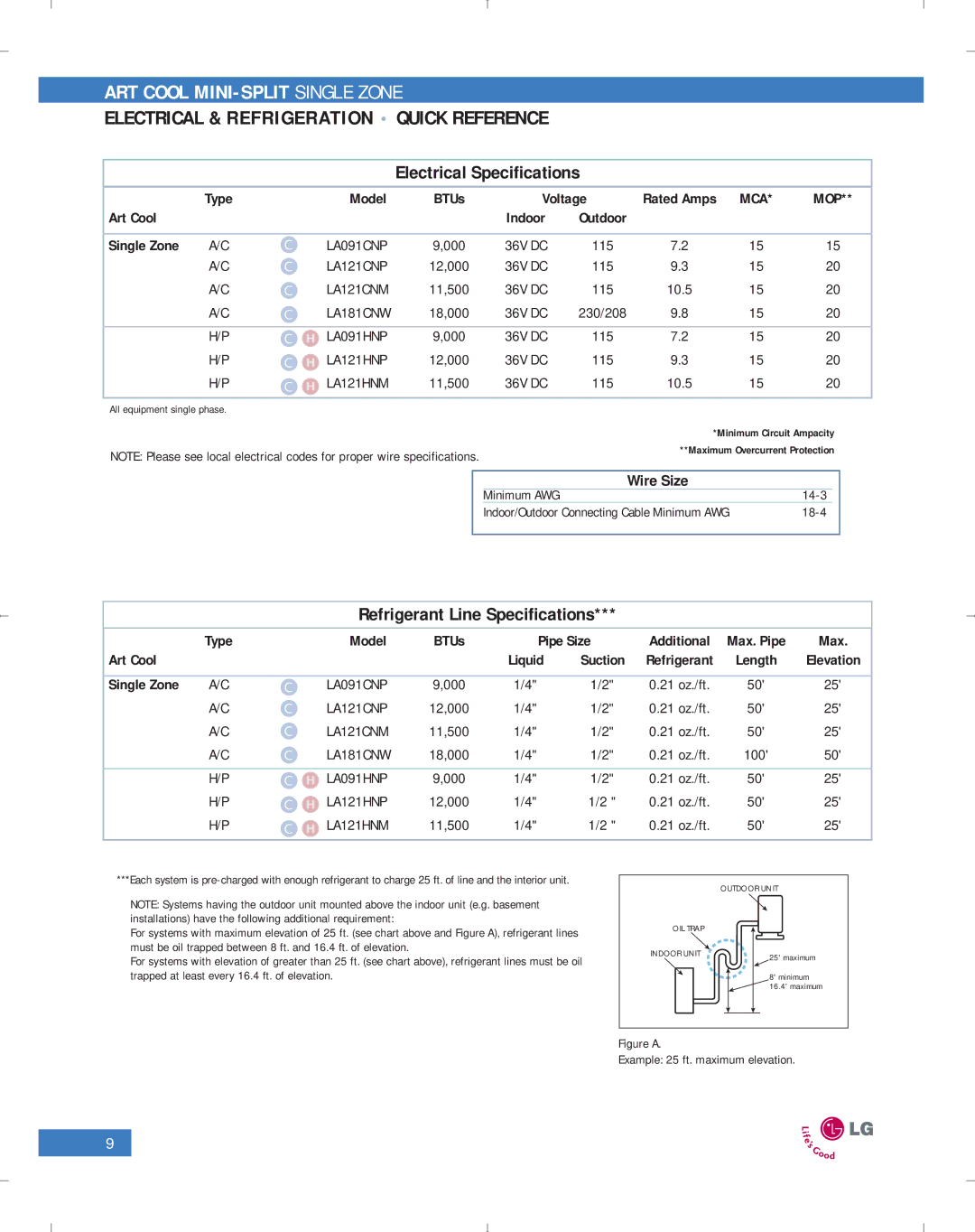
NOTE: Systems having the outdoor unit mounted above the indoor unit (e.g. basement installations) have the following additional requirement:
For systems with maximum elevation of 25 ft. (see chart above and Figure A), refrigerant lines must be oil trapped between 8 ft. and 16.4 ft. of elevation.
For systems with elevation of greater than 25 ft. (see chart above), refrigerant lines must be oil trapped at least every 16.4 ft. of elevation.
| OUTDOOR UNIT |
OIL TRAP |
|
INDOOR UNIT | 25' maximum |
| |
| 8' minimum |
| 16.4' maximum |
Figure A.
Example: 25 ft. maximum elevation.
9