Configurations
The Micro SmartSwitch can be configured to fit several power distribution requirements.
Configuration 1
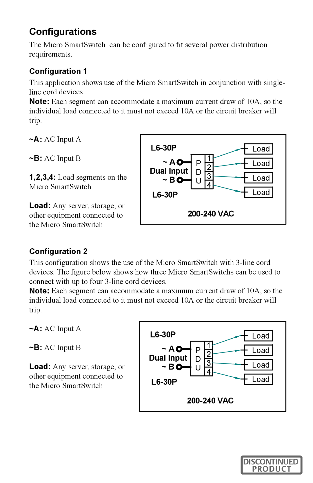
This application shows use of the Micro SmartSwitch in conjunction with single- line cord devices .
Note: Each segment can accommodate a maximum current draw of 10A, so the individual load connected to it must not exceed 10A or the circuit breaker will trip.
~A: AC Input A
~B: AC Input B
1,2,3,4: Load segments on the Micro SmartSwitch
Load: Any server, storage, or other equipment connected to the Micro SmartSwitch
Configuration 2
| 1 | ||
~ A | DP | ||
2 | |||
Dual Input | |||
~ B | U | 3 | |
|
| 4 | |
|
| ||
| |||
Load
Load
Load
Load
This configuration shows the use of the Micro SmartSwitch with
Note: Each segment can accommodate a maximum current draw of 10A, so the individual load connected to it must not exceed 10A or the circuit breaker will trip.
~A: AC Input A
~B: AC Input B
Load: Any server, storage, or other equipment connected to the Micro SmartSwitch
| 1 | ||
~ A | DP | ||
2 | |||
Dual Input | |||
~ B | U | 3 | |
| 4 | ||
|
| ||
Load
Load
Load
Load
DISCONTINUED
PRODUCT