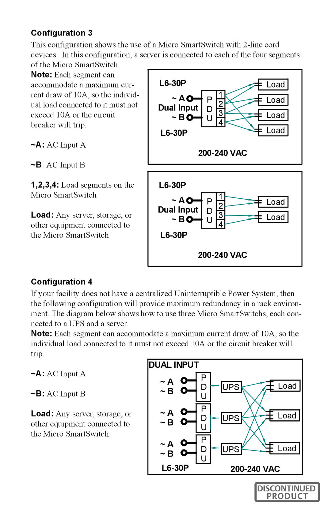
Configuration 3
This configuration shows the use of a Micro SmartSwitch with
of the Micro SmartSwitch. |
|
|
|
|
|
|
|
|
|
|
|
|
|
|
|
|
|
|
|
| |
Note: Each segment can |
|
|
|
|
|
|
|
|
| |
accommodate a maximum cur- |
|
|
|
|
|
| Load |
|
| |
|
|
|
|
|
|
|
| |||
|
|
|
|
|
|
|
| |||
rent draw of 10A, so the individ- |
| ~ A | DP | 1 |
|
|
|
|
|
|
|
|
|
| Load |
|
| ||||
ual load connected to it must not |
| 2 |
|
|
|
|
| |||
| Dual Input |
|
|
|
|
| ||||
|
|
|
|
|
|
| ||||
exceed 10A or the circuit |
| ~ B | U | 3 |
|
|
| Load |
|
|
|
|
|
|
|
| |||||
|
|
|
|
|
| |||||
| 4 |
|
|
| ||||||
breaker will trip. |
|
|
|
|
|
|
| |||
|
|
|
|
|
|
| ||||
~A: AC Input A |
|
|
|
|
|
| Load |
|
| |
|
|
|
|
| ||||||
|
|
|
|
|
| |||||
~B: AC Input B |
|
|
|
|
|
|
|
|
|
|
|
|
|
|
|
|
|
|
|
| |
1,2,3,4: Load segments on the |
|
|
|
|
|
|
|
| ||
Micro SmartSwitch |
|
|
|
|
|
|
|
|
| |
~ A | DP | 1 |
|
|
|
|
|
| ||
|
|
| Load |
|
| |||||
|
| 2 |
|
|
|
|
| |||
Load: Any server, storage, or | Dual Input |
|
|
|
|
| ||||
|
|
|
|
|
| |||||
~ B | U | 3 |
|
|
| Load |
|
| ||
|
|
|
| |||||||
other equipment connected to | 4 |
|
|
|
|
|
| |||
|
|
|
|
|
| |||||
the Micro SmartSwitch |
|
|
|
|
|
|
|
|
| |
Configuration 4
If your facility does not have a centralized Uninterruptible Power System, then the following configuration will provide maximum redundancy in a rack environ- ment. The diagram below shows how to use three Micro SmartSwitchs, each con- nected to a UPS and a server.
Note: Each segment can accommodate a maximum current draw of 10A, so the individual load connected to it must not exceed 10A or the circuit breaker will trip.
~A: AC Input A
~B: AC Input B
Load: Any server, storage, or other equipment connected to the Micro SmartSwitch
DUAL INPUT
~ A | P |
| Load | |
D | UPS | |||
~ B | ||||
U |
|
| ||
|
|
| ||
~ A | P |
| Load | |
D | UPS | |||
~ B | U |
|
| |
|
|
| ||
~ A | P |
| Load | |
D | UPS | |||
~ B | ||||
U |
|
| ||
| ||||
| ||||
DISCONTINUED
PRODUCT